Location
Mount Vernon, WA 98274
Location
Mount Vernon, WA 98274

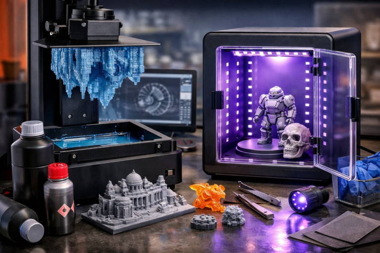
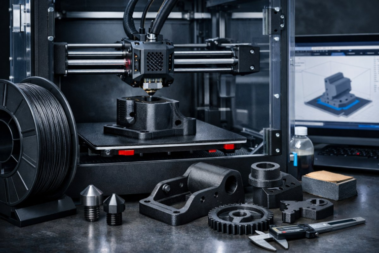
Discover how to dial in every setting for PETG printing on a desktop FDM machine. From bed preparation to fine-tuning extrusion and cooling, this guide reviews essential components-from high-performance filament to hotend upgrades-that elevate your printing game and unlock durable, warp-free parts.
Additive manufacturing opens a gateway to rapid prototyping and customized production. Among thermoplastic materials, PETG strikes a balance between PLA’s ease of use and ABS’s toughness. Layer adhesion is superb, parts resist moisture and wear, and chemical resistance is high enough for functional prototypes. Yet PETG does demand careful attention to bed adhesion, temperature control, and tooling. This guide takes you through each step, reviewing the technique and highlighting key components that transform frustrating prints into reliable successes. By the end, you’ll have the confidence to print complex geometries and load-bearing parts that stand up to real-world use.
First, understand why PETG deserves a place on your spool rack. Its amorphous molecular structure bonds layers more securely than semi-crystalline plastics, eliminating many fracture points. It shrugs off impact better than standard PLA, so gears and hinges operate more smoothly over time. High glass transition temperature also means parts tolerate moderately elevated temperatures-think dashboard clips or kitchen tools. Sustainability advocates will appreciate that many PETG formulations incorporate recycled material, reducing plastic waste and carbon footprint. In short, PETG bridges form and function for makers, engineers, and hobbyists alike.
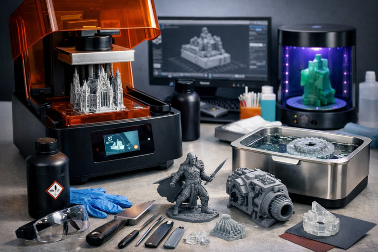
Before a single line extrudes, invest in a flat, stable bed surface. A PEI sheet offers excellent adhesion for PETG without glue or tape. Its textured surface gives just enough tooth for the first layers to grip, while allowing clean release as the part cools. Secure the sheet firmly to your bed with spring-steel clips, checking for flatness. A warped PEI sheet can induce uneven first layers and lead to warping or layer shifting later. Once leveled, mark your zero height position and save it as the printer’s home offset. This consistency speeds up calibration and reduces frustrations over time.
Next, consider upgrading your extruder and hotend assembly. PETG softens around 80°C but can string and ooze if mixed with residual molten material inside a PTFE-lined hotend. An all-metal hotend prevents filament degradation at higher temperatures, clearing the path for smoother extrusion. Quality nozzles made from hardened steel resist abrasive fillers. If you plan to experiment with carbon-fiber-reinforced PETG, hardened nozzles are essential. After installation, tighten the nozzle and heat break firmly, then heat the block to operating temperature and re-tighten to account for thermal expansion. A secure hotend means consistent melting and flow.
Calibrating flow rate is the next pillar of success. PETG’s density differs slightly from PLA, and its shrinkage coefficient is lower. Start by printing a simple 20 mm calibration cube at 0 % flow multiplier. Measure wall thickness with a precision digital caliper, then adjust your slicer’s extrusion multiplier until the walls match the intended thickness. An under-extruded cube will reveal gaps between lines; over-extrusion creates bulges. Getting flow dialed in ensures dimensional accuracy, crisp detail, and reliable part strength.
Temperature towers help pinpoint the sweet spot for your filament batch. Create a model that changes temperature every 10 °C over a range from 220 °C to 260 °C. During the print, observe layer adhesion, stringing, and surface gloss. Cooler regions will show poor fusion between layers; hotter regions may exhibit droopy overhangs or heavy stringing. For most PETG spools, the ideal window lands between 240 °C and 250 °C. Note that elevated temperatures can increase oozing, so pairing the right heat with retraction and cooling settings is crucial.
Retraction settings often puzzle newcomers. PETG behaves differently from PLA: too much retraction can clog a Bowden tube, while too little invites strings that mar surface quality. For direct-drive extruders, start with a retraction distance of 1 mm to 2 mm at a speed of 20 mm/s. Bowden setups may require 4 mm to 6 mm. Print a simple stringing test-two pillars separated by 50 mm with a short travel path between them. Tweak retraction incrementally until strings vanish without triggering under-extrusion at the start of new lines.
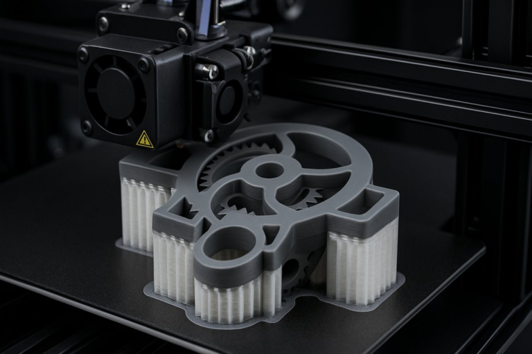
Cooling models with PETG calls for a measured approach. Unlike PLA, overzealous fans can cool the material too quickly, compromising layer bonding and causing weak interlayer adhesion. Begin with 0 % fan for the first few layers to secure base adhesion. Then ramp up to 30 % to 40 % for bridging sections and fine details. Print a bridging test-horizontal spans at various lengths-to verify that filament bridges gaps cleanly. If sagging occurs, nudge the fan speed upward in small increments until your bridges look taut and straight.
Leveling and first-layer tuning cannot be overstated. A gap halfway between nozzle and bed spells a missing foundation; press the nozzle flush, and the filament smears into a pancake. Aim for a paper-thin fingerprint smear on a sheet. Use live bed-mesh compensation if your firmware supports it, and print a large skirt or raft to prime the nozzle and stabilize flow before critical features lay down. Watch for under-extrusion or bulging lines and adjust Z-offset on the fly to hit that sweet spot consistently across the build surface.
Add a brim or raft for models with small footprints or tall, narrow geometry. PETG resists warping better than ABS, but thin fins or corners can still lift if cooling unevenly. A 5 mm brim typically delivers enough surface area to keep edges anchored without leaving permanent marks. For delicate details, a thin raft can isolate the part from minor bed adhesion inconsistencies, then peels away cleanly once adequate cooling time has passed.
Post-processing PETG parts is straightforward but rewarding. Sanding with 200- to 400-grit wet-dry paper smooths layer lines; following with finer grits polishes the surface. A light acetone vapor bath can slightly fuse layers and enhance gloss, but PETG is less responsive to solvent vapor than ABS. For functional parts, coat exposed threads with a thin layer of petroleum jelly or silicone spray to reduce friction in each assembly. If water resistance is critical-for example, custom plumbing fittings-apply a food-safe epoxy or conformal coating to seal any micro-gaps.
Real-world examples underscore why fine-tuned PETG printing matters. Engineers have fabricated custom drone gimbal mounts that endure twisting forces; medical designers prototype ergonomic handles for equipment without risk of brittle failure; hobbyists create waterproof enclosures for outdoor sensors. Each application relies on precise layer adhesion, dimensional fidelity, and reliable tooling that this guide helps you achieve. Armed with the right components and settings, you’ll transform your printer into a facility for robust, functional parts.
Now that you’ve explored bed surfaces, hotend upgrades, flow calibration, retraction, cooling, and finishing, it’s time to embark on your own PETG projects. Document your settings, record acceptable tolerances, and refine over successive prints. Embrace curiosity: test recycled or bio-PETG variants, explore composite blends with wood or metal particles, or integrate flexible sections for snap-fit assemblies. Each tweak reveals fresh insights into additive manufacturing’s versatile potential.
As you master PETG printing, you’ll discover more than just technical proficiency-you’ll cultivate patience, creativity, and a deep appreciation for the material science behind each layer. This journey transforms digital designs into tangible reality, and the quality components you choose make every print an opportunity to learn. Preheat your bed, click Print, and watch as PETG elevates your next breakthrough from concept to creation.