Location
Mount Vernon, WA 98274
Location
Mount Vernon, WA 98274

Discover how trochoidal milling can transform your CNC milling projects with smoother cuts, longer tool life, and faster cycle times. This guide breaks down tool selection, CAM settings, machine setup, and troubleshooting to help you harness the power of dynamic toolpaths in aluminum, steel, and more. Give your next part the precision and efficiency edge with these practical tips.
In the world of CNC milling, unlocking efficiency and precision often feels like chasing a moving target. Trochoidal milling, a dynamic roughing technique that uses constant chip thickness and small radial engagement, offers a way forward. By maintaining a steady load on the cutter, it reduces heat buildup, extends tool life, and accelerates material removal. Whether you’re machining a deep pocket in aluminum or roughing out a steel block, mastering trochoidal toolpaths can transform your workflow. This guide walks through every stage-from choosing the right end mill to dialing in CAM parameters-so you can confidently integrate trochoidal strategies into your projects.
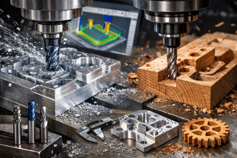
At its core, trochoidal milling replaces heavy, wide cuts with a spiral or looping motion that keeps the radial depth of cut shallow. Instead of plunging the cutter across the entire width of a slot, the tool follows a circular arc while feeding axially. Each pass removes a thin slice of material, which means less stress on the cutter, lower spindle loads, and smoother chip evacuation. The result is a cooler cutter, fewer tool changes, and feed rates you’ll want to push higher than in conventional roughing.
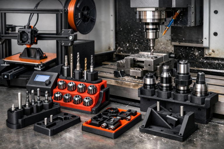
Tool selection is crucial. Start with a solid carbide end mill designed for high-feed or dynamic milling. Choose a diameter that matches your pocket or slot width but be mindful of flute count: 3-flute cutters excel in aluminum thanks to their larger flute volume, while 4-flute tools shine in steel for rigidity and surface finish. Coatings such as TiAlN or DLC can further improve heat resistance when tackling hardened alloys. For deeper pockets, consider varying your tool lengths: a stub-length cutter offers maximum rigidity, while an extended reach tool lets you reach tight features with minimal chatter.
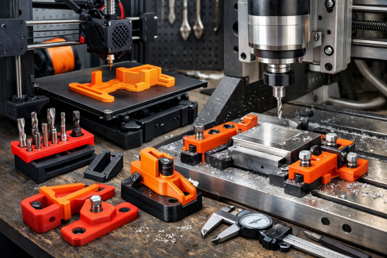
Before touching the workpiece, set up your CNC mill with care. A precision vise provides firm, repeatable clamping-avoid overhang that invites vibration. Clean the table and jaws to ensure flat contact. Zero your axes with an edge finder or probing system, then verify the Z-zero on a known surface. If your machine offers coolant through the spindle, engage it to help evacuate chips and control temperature. Dry runs can reveal potential collisions and ensure your trochoidal path doesn’t encroach on clamps or fixtures.
Programming a trochoidal toolpath in CAM software requires attention to three key parameters: step-over (radial depth of cut), step-down (axial depth per pass), and feed rate. A common starting point is a radial step-over of 5-20 percent of the cutter diameter, paired with an axial step-down that doesn’t exceed the tool’s flute length or the material’s machinability. From there, set a modest chip thickness-often 0.002-0.006 inches per tooth-then let the software calculate the feed rate based on your spindle speed. Simulate the path in the CAM environment to confirm continuous engagement and smooth arcs. Look for any sudden reversals or sharp corners that might stall motion.
Material choice influences your parameters. In aluminum alloys (6061, 7075), you can push feed rates aggressively thanks to the metal’s machinability. Slightly increase radial engagement to speed up removal, but watch chip size: packed chips can re-cut and generate heat. In tougher materials like 304 stainless steel or titanium, keep radial steps below 10 percent of diameter and slow your feed slightly to avoid work hardening. Coolant pressure and nozzle positioning become critical to flush chips from deep features and prevent built-up edge.
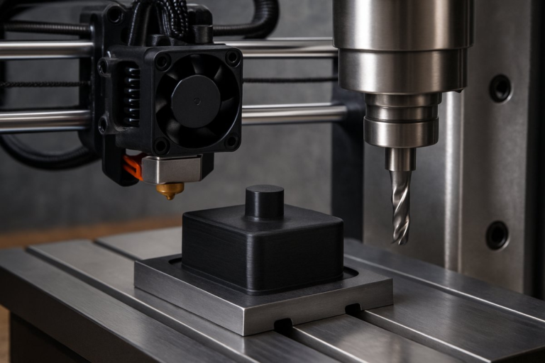
When you’re ready for the first cut, slow your spindle ramp during entry to prevent tool deflection. Listen closely to the machine-uniform, crisp rasping indicates stable cutting, while screeching or knocking signals too much load or chatter. Inspect the chips: consistent, uniform swirls point to even engagement, while stringy, dull ribbons suggest incorrect rpm or worn geometry. If you see discoloration on your end mill or dark, fused chips, reduce feed or increase coolant flow immediately.
After the roughing passes, you’ll often switch to a finishing end mill. A 4-flute square end mill or a ball-nose cutter can clean up walls and bottom surfaces with tighter step-over values. For pockets, a fine step-over of 10-15 percent of diameter yields crisp contours without visible scallops. In corners, consider a corner-rounding tool or a chamfer mill to remove sharp edges and improve toolpath transitions in subsequent assembly.
Once the CNC program completes, remove the part and inspect critical dimensions. A dial indicator or a coordinate measuring machine (CMM) can verify flatness and parallelism of pocket floors. Deburr with a handheld countersink or a ceramic stone-focus on edges left by trochoidal paths, which may form slight lips. If surface finish matters, a light bead blast or a scotch-brite pad can provide a uniform matte texture without altering tolerances.
Troubleshooting common issues keeps you productive. If face chipping occurs, check your radial depth of cut and slow the spindle entry. Persistent chatter may call for a shorter end mill or a higher spindle speed to shift resonance. When chips accumulate in deep slots, reposition coolant nozzles or add air blast to clear the path. And remember that fixture rigidity matters: even the best toolpath fails if the workpiece moves under load.
• Loose workholding? Tighten the vise or add parallels to lift the part for better clamping.
• Excessive tool wear? Opt for a coated carbide end mill or reduce chip load.
• Inconsistent surface finish? Adjust final step-over or slow the finishing feed rate.
By integrating trochoidal milling into your CNC strategy, you’ll reduce cycle times and protect expensive tooling. Modern CAM systems make it easier than ever to generate dynamic toolpaths, but the principles remain rooted in material science and machine behavior. Start with small pockets or simple slots, then apply your findings to complex cavities and deep features.
Trochoidal milling might seem advanced, but with the right cutter, careful setup, and a bit of experimentation, you’ll see transformative results. Reduced heat, improved chip control, and cleaner finishes all stem from keeping the tool engaged just enough to cut efficiently. As you refine your parameters, track tool life and cycle time data to quantify gains. Over time, this method becomes a powerful arrow in your CNC arsenal-one that turns raw blocks of metal into precision parts faster and more reliably than ever before.