Location
Mount Vernon, WA 98274
Location
Mount Vernon, WA 98274
Discover how to combine fused deposition modeling (FDM) 3D printing with CNC routing to achieve precision finishes on parts. This guide walks you through selecting materials, calibrating your printer, slicing settings, and even mounting and milling your prints for a truly professional result.
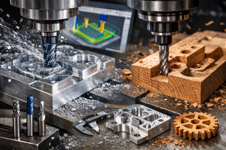
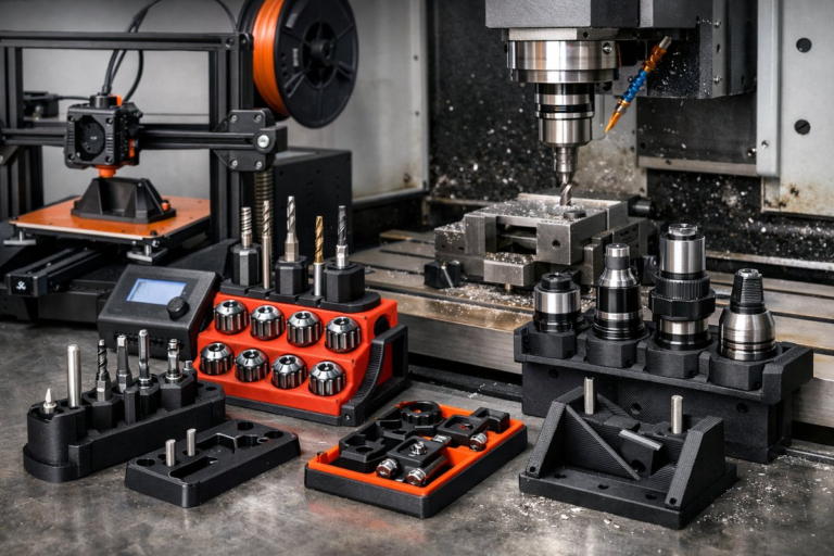
Additive manufacturing is celebrated for its ability to build complex geometry layer by layer, but the true artistry often lies in marrying that process with subtractive techniques to achieve flawless surface quality and tight tolerances. In this guide, we’ll explore how to leverage a desktop FDM 3D printer together with a CNC router or milling machine to craft parts that look and feel like they came straight out of a professional machine shop. From design considerations to tool selection and workflow tips, you’ll gain the confidence to try hybrid manufacturing at home or in your workshop.
Everything starts in CAD. When planning a part for hybrid production, think about which surfaces need high precision and which can remain as-printed. Flat mounting faces, keying features, and alignment holes should be designed with both 3D printing tolerances and milling toolpaths in mind. Maintain a small buffer (0.5-1 mm) between fine features and the build orientation to ensure there’s material available for subsequent CNC passes. Export your model in a high-resolution STL or STEP format to preserve detail.
A well-calibrated 3D printer lays the foundation for successful finishing. Begin by leveling the build plate and ensuring stable extrusion. Use a standard 0.4 mm brass or plated steel nozzle for general parts; you can swap to a hardened steel nozzle if you plan to print abrasive composites. Load a high-quality PLA or PETG filament-these materials offer good rigidity and minimal warping. Adjust your slicer settings for 0.2 mm layer height, 20 % infill, and a moderate wall count (3 walls) to balance strength and material usage. Print at a nozzle temperature of around 200 °C (PLA) or 240 °C (PETG) and plate temperature of 60 °C if available.
Orient parts so that critical faces that will be machined are as close to horizontal as possible. This minimizes uneven layering and makes it easier to hold the part during CNC operations. Generate supports only where necessary; you don’t want support marks on surfaces destined for milling. Use breakaway or water-soluble supports in peripheral areas to reduce post-processing cleanup.
Select a slicer that allows custom G-code insertion before and after the print cycle. This is essential if you want to add tool-change commands later or embed fiducial markers for CNC alignment. Export the print G-code and annotate the coordinates of three noncollinear points on the build plate; these will serve as registration references when you switch to the CNC environment.
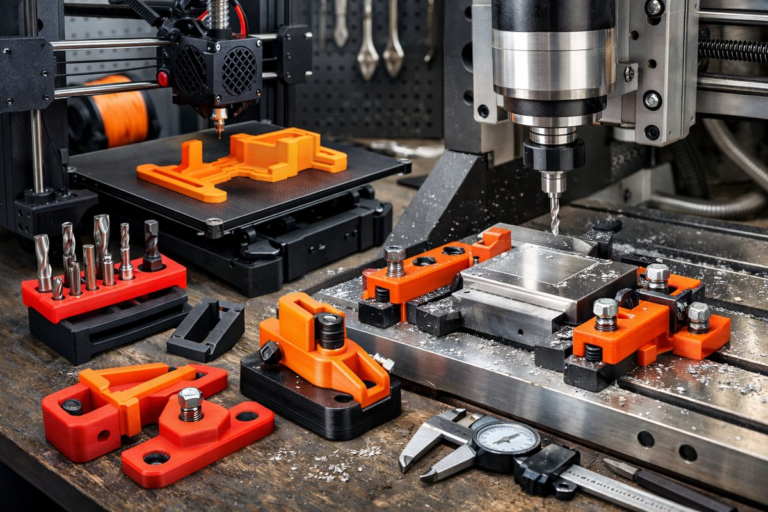
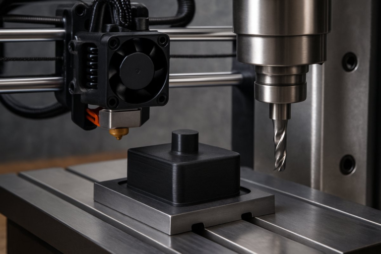
Once your part is printed, remove it gently from the build plate and trim any stray filaments. Clean it with isopropyl alcohol if needed. Transfer it to the CNC router bed using a dedicated fixture or vacuum table. Secure the part with double-sided tape or low-profile clamps-avoid hidden screws that could shift under milling forces. Use the same three reference points you noted during slicing to establish the X, Y, and Z origin in your CAM software.
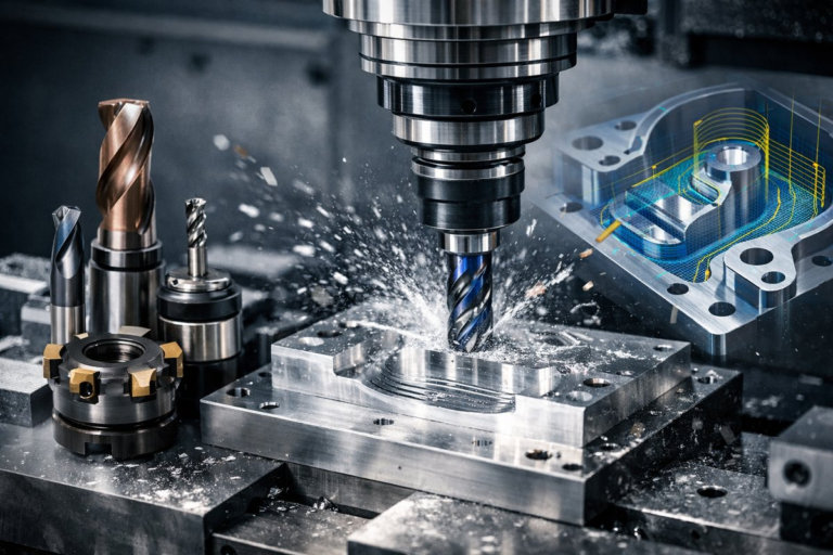
For initial passes, a 3 mm flat end mill works well to remove layer lines and flatten broad surfaces. Follow up with a 1 mm ball nose or tapered end mill to refine curves and edge details. Carbide tools are a must for longevity and rigidity. Make sure your spindle speed and feed rates suit plastic: around 12,000 RPM and 1,000 mm/min feed speed helps prevent melting or chip welding. Keep depth of cut shallow-0.3 mm per pass-to limit cutting forces and avoid lifting the part.
Run a roughing pass to knock down most of the excess material. Leave about 0.2 mm of scallop material to avoid overloading your finishing tool. Clear chips frequently and blow compressed air to keep the toolpath clean. After roughing, swap to your finishing bit and slow down the spindle to 8,000 RPM. A light air blast during the finish pass helps achieve a mirror-like surface.
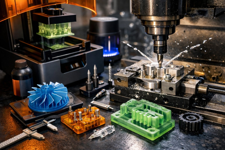
After milling, inspect the part with digital calipers and a dial indicator to verify flatness and dimensions. Sand edges by hand starting with 400 grit and progressing to 1,000 grit for a silky finish. If you’re working with ABS, a quick vapor-smoothing step can further erase layer lines. For PETG or PLA, a thin coat of clear spray lacquer provides UV protection and a uniform sheen.
Keep a shared tool library in your CAM software with saved tool definitions and machining strategies. Label your fixture plates and maintain a photo log of part orientations to speed up setup. If you plan to produce multiple parts, create a nesting template in your CAM program so you can machine two or three prints in one go. And always measure your finished parts against a known gauge block to catch calibration drift over time.
Many hobby-grade CNC controllers accept G-code from 3D slicers directly, but you may need to reprocess it in CAM software to add tool changes and ramp strategies. Consider using a unified platform or plugin that bridges your slicer and your CNC controller, reducing manual edits. Some open-source CNC firmware even supports built-in macro functions to automate registration and coordinate offsets.
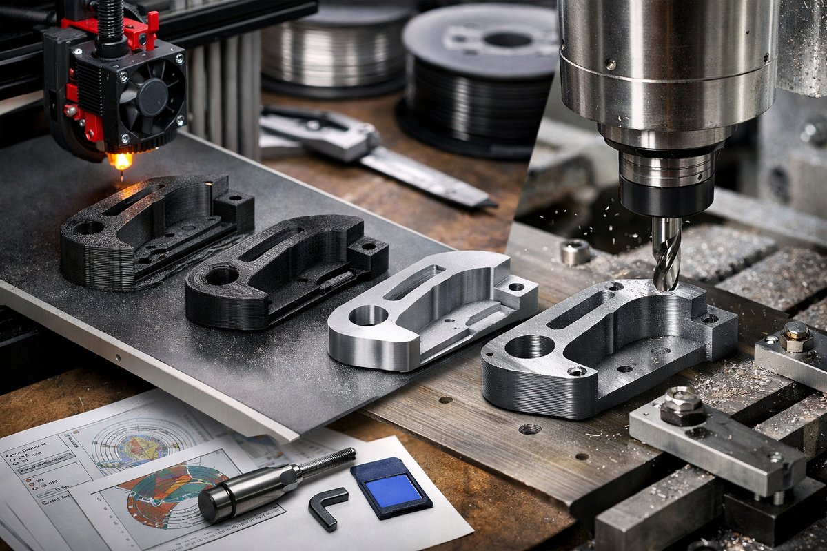
The intersection of additive and subtractive manufacturing unlocks a realm of possibilities-from rapid prototyping to end-use parts with tight tolerances. By combining FDM printing with thoughtful CNC finishing, you gain both the creative freedom of 3D design and the surface quality associated with traditional machining. The modest investment in a quality router, a handful of carbide end mills, and a few hours of calibration can transform your prints from functional prototypes into polished components ready for real-world applications. Embrace the quiet discipline of subtraction, and watch each part emerge with the precision you envisioned.