Location
Mount Vernon, WA 98274
Location
Mount Vernon, WA 98274

Discover how adaptive clearing revolutionizes CNC milling by maintaining constant tool engagement, reducing cycle times, and extending tool life. This guide breaks down machine setup, tooling choices, CAM parameters, and finishing strategies so you can implement high-efficiency milling on your next project.
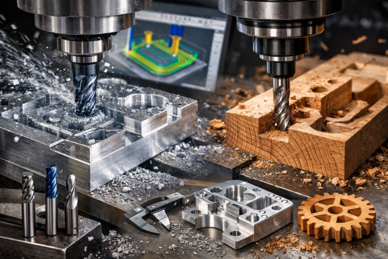
Adaptive clearing has become a go-to strategy for experienced machinists and newcomers alike searching for a smarter way to remove material without overloading tools or the spindle. Unlike traditional pocketing, where engagement varies drastically, adaptive clearing keeps the cutting tool bite consistent as it carves through metal, plastic, or composites. That reliability unlocks faster feed rates, steadier forces, and longer tool life. Whether you run a three-axis CNC router or a five-axis milling center, understanding how to integrate adaptive toolpaths can take your efficiency and surface finishes to the next level.
Before diving into a project, it’s crucial to evaluate your machine’s capabilities. A rigid frame, precise ballscrew-driven axes, and a spindle rated for high rpm will handle the dynamic loads of high-efficiency passes. Check maintenance logs for backlash or worn guides, and recalibrate your machine if you notice any chatter or inaccuracy when jogging across axes. Even small deflections can compound when pushing feed rates beyond typical roughing speeds.
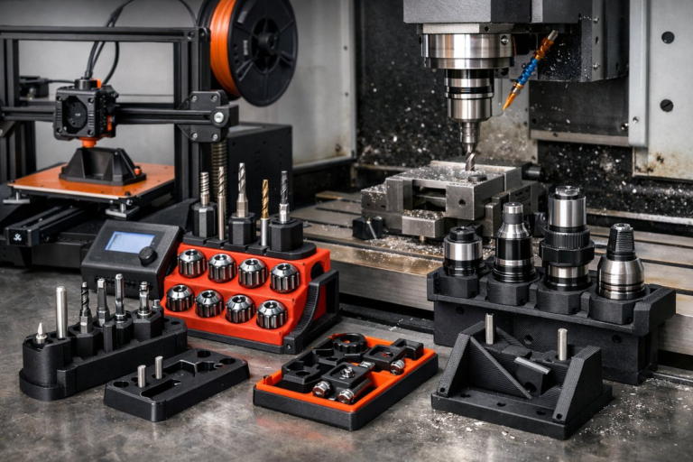
Tooling selection is the backbone of adaptive clearing success. Carbide end mills with four or more flutes strike a balance between chip clearance and shear strength. For steel and harder alloys, choose geometry optimized for high-speed machining: a polished fluting surface to resist built-up edge and a balanced helix angle-typically between 30° and 40°-to ensure smooth chip evacuation. Shorter tool overhang reduces deflection, so pair your end mills with a precision collet chuck or shrink-fit holder. If your machine supports through-spindle coolant, a toolholder with internal coolant channels can help flush chips away and keep cutting temperatures under control.
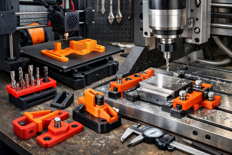
Setting up workholding goes hand in hand with tool rigidity. A well supported vise, modular fixturing kit, or tombstone fixture can anchor parts securely without disturbing your zero reference. Make sure parallels or step blocks are clean and square, and apply consistent torque on vise screws. When possible, locate datum features within reach of your adaptive toolpath but away from the heaviest cuts to minimize fixture interference. Soft jaws or dedicated sacrificial plates can help you hold complex shapes while ensuring a solid grip.
Once your machine and tooling are in place, open your CAM software and prepare the stock model. Define your material block, aligning datum planes to your machine’s zero. When configuring the adaptive clearing operation, set your maximum stepdown for roughing according to tool diameter and material hardness. A stepdown of 10-15% of the cutter diameter is a safe starting point for most metals. For plastics or softer materials, you can push that closer to 25% while monitoring chip size and evacuation.
The defining parameter of adaptive clearing lies in the radial stepover. Rather than hogging out large pockets with a full-size cutter, the tool engagement remains constant-often between 5% and 20% of cutter diameter-so forces stay predictable. Input a stepover of 10-15% to see significant cycle-time reductions without sacrificing tool life. Combine that with high feed per tooth-around 0.002″-0.005″ for common alloys-and you’ll notice the spindle load graph smoothing out, free of the peaks typical in traditional zig-zag roughing.
If your CAM package supports linking moves or ramping, enable those to keep the cutter engaged at all times, avoiding abrupt entry into the material. Consistent engagement means less spindle shock and smoother power draw. Some systems offer adaptive linking at corners, rounding internal radii automatically so the tool doesn’t decelerate sharply at abrupt direction changes. This feature is especially helpful when cutting contoured cavities or pockets with complex outlines.
After simulating the toolpath and verifying there are no collisions or gouges, generate g-code and upload it to your CNC controller. Before committing to a full run, always perform a dry cycle-spindle off, axis moves only-to confirm your zero references and tool lengths. If your control supports live load monitoring, watch the load meter during a partial test cut. Expect to see a relatively flat load curve rather than spikes. If you spot chatter or load surges, reduce feed per tooth slightly or adjust your stepover downward by 2-3%.
Once the main adaptive clearing pass is complete, you’ll have a rough shape with minimal scallop height. Now switch to a finishing strategy: a high-speed spiral or Z-level pass at a shallow stepdown (0.002″-0.005″) to refine surface integrity. Use a ball nose cutter or a corner-radius end mill for complex surfaces, matching the cutter radius to your desired fillets. These lighter passes won’t add much cycle time compared to the initial rough, and they bring out crisp edges and smooth walls without requiring manual deburring.
Throughout the process, keep a log of your parameters and machine response. Note spindle load, visible tool wear, and any tool deflection observed in finished parts. With each new job, you’ll refine stepdowns, stepovers, and feed rates for different materials-be it aluminum 6061, tool steel, or nylon. Over time, your database of optimized settings will shorten setup and boost productivity across diverse projects.
Adaptive clearing transforms rough milling from a guess-and-check routine into a science of predictable engagement. The constant chip load simplifies parameter tuning, while high feed rates and efficient chip evacuation cut cycle times drastically. With the right carbide end mills, precision holders, and workholding, you’ll achieve greater throughput without sacrificing quality. Whether you build precision brackets, custom fixtures, or functional prototypes, adaptive clearing empowers you to focus on design refinement rather than wrestling with tool deflection or premature wear.
Ready to bring high-efficiency milling into your workshop? Start by assessing your machine’s rigidity and ensuring it’s up for dynamic cutting. Invest in a reliable set of carbide end mills, a precision collet chuck, and through-coolant capability if your spindle allows. Then experiment with adaptive clearing parameters in your CAM software, gradually raising feed per tooth and stepover until you find the sweet spot between speed and tool life. With each project, you’ll unlock new levels of performance, leaving behind the limitations of outdated roughing routines and embracing a future where your machine hums in constant, efficient motion.