Location
Mount Vernon, WA 98274
Location
Mount Vernon, WA 98274
Explore a hybrid workflow that combines the creative freedom of fused filament fabrication with the precision of CNC milling. This guide walks you through selecting materials, setting up toolpaths, and integrating key components like nozzles and end mills to achieve flawless surface finish and tight tolerances.
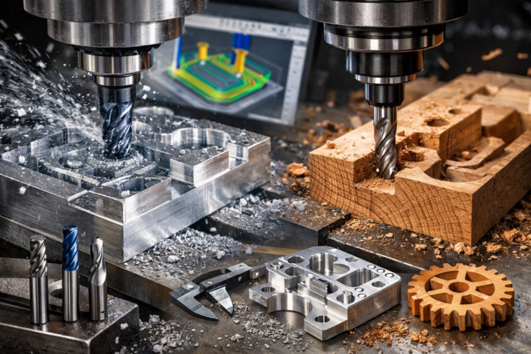
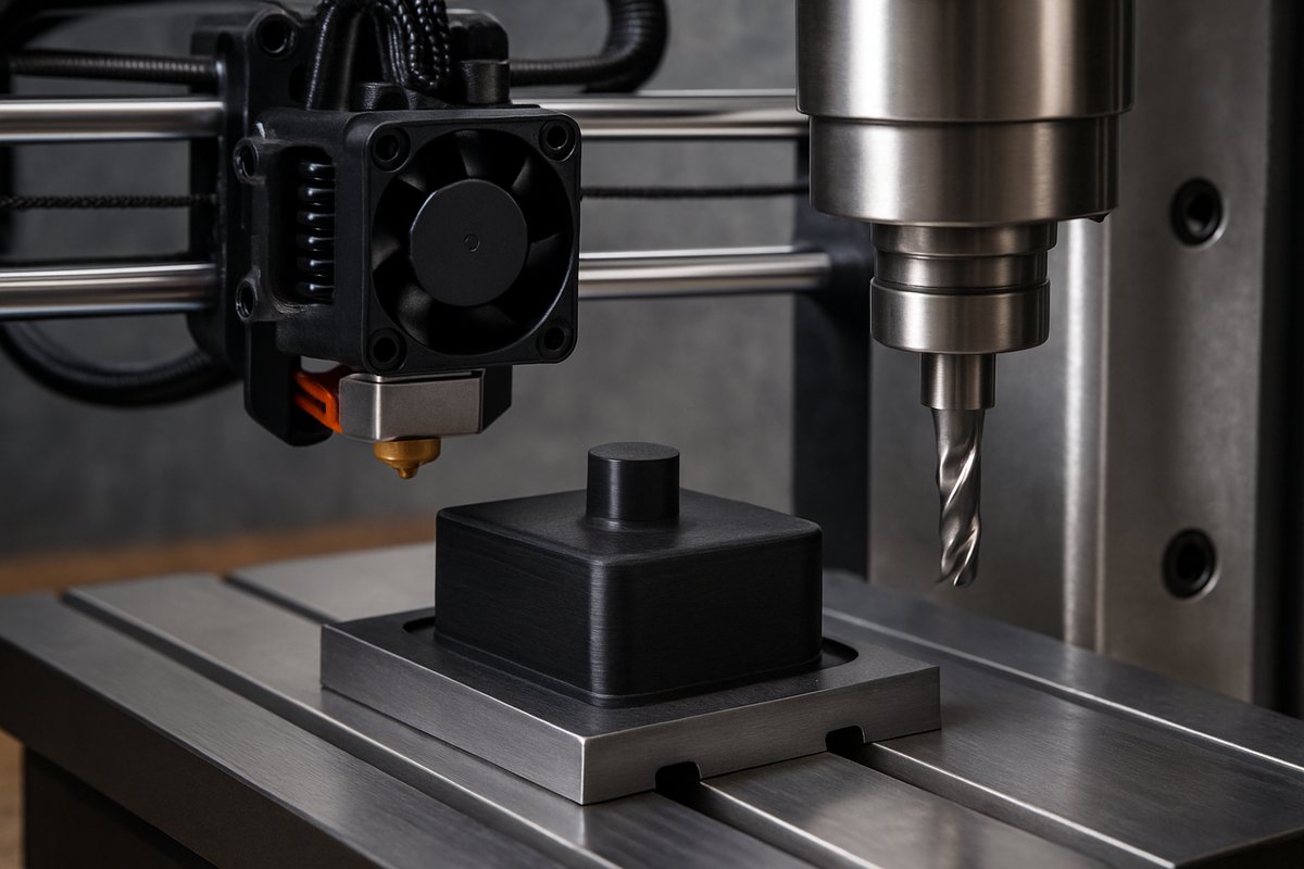
Additive manufacturing excels at rapid shape realization, but droplet lines, layer steps, and minor distortions can limit its use in high-precision applications. By pairing fused filament fabrication (FFF) with a post-print CNC milling pass, you can unlock smooth surfaces, crisp edges, and repeatable dimensional accuracy. This hybrid approach harnesses the best of both worlds: the creative geometry freedom of 3D printing and the exacting subtractive discipline of CNC machining.
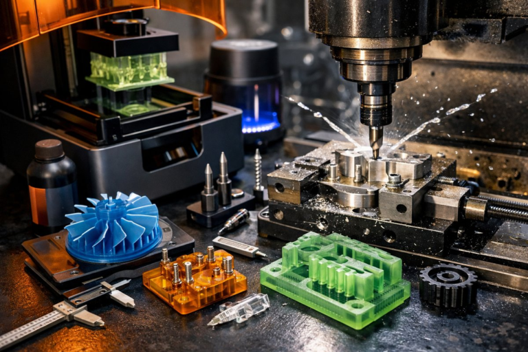
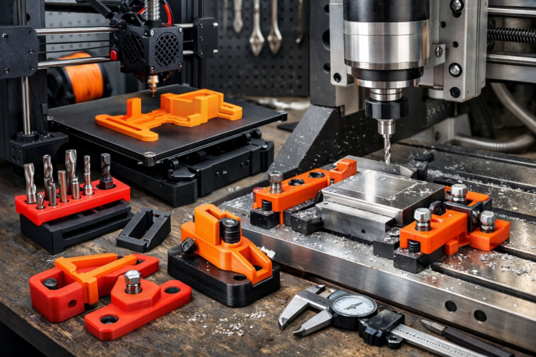
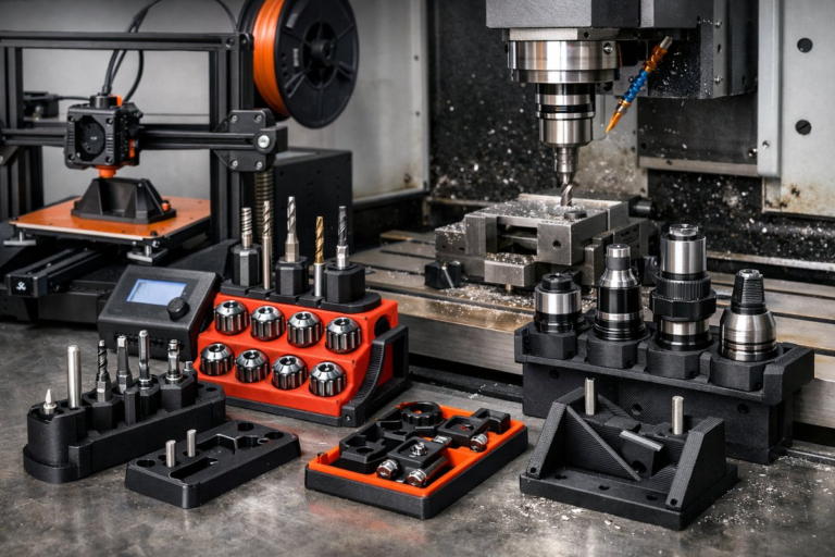
Before diving in, gather the essentials: a reliable desktop FFF printer, a compact three-axis CNC mill or router, CAM software that supports 3D models, and a collection of finishing bits. You’ll also need basic measuring and fixturing tools-a digital caliper, a precision vacuum hold-down or clamping kit, plus safety equipment like a dust mask and hearing protection. Once you have these on hand, you’re ready to tackle a project that starts in plastic filament and ends in refined, production-ready parts.
Begin by choosing the right filament. PLA is easy to print and machines cleanly, making it ideal for your first hybrid experiment. If you need higher heat resistance or impact strength, consider PETG or nylon, but remember these materials can be a bit more gummy under the cutter. For complex geometries, adopt a modest layer height of 0.12-0.16 mm to limit the amount of material a ball-nose end mill must remove later. A 0.4 mm brass nozzle works well for most shapes, balancing flow rate and resolution.
After printing, carefully remove any support material and trim stray strings. Lightly sand visible layer lines with 220-grit sandpaper to reduce deep scratches that might trip up the milling bit. Clean the part with isopropyl alcohol or warm, soapy water to eliminate oils and debris. When the surface is free of contaminants, you’re ready for the subtractive stage.
Secure the part on your CNC bed using a low-profile vacuum hold-down or a set of soft jaws if your machine offers a vice. For small parts, a wood spoil board with double-sided tape can also work-just ensure it’s flat and stable. Double-check that the printed piece is rigidly fixtured to prevent chatter or lift during milling. Proper fixturing is the bridge between a good print and a perfectly finished component.
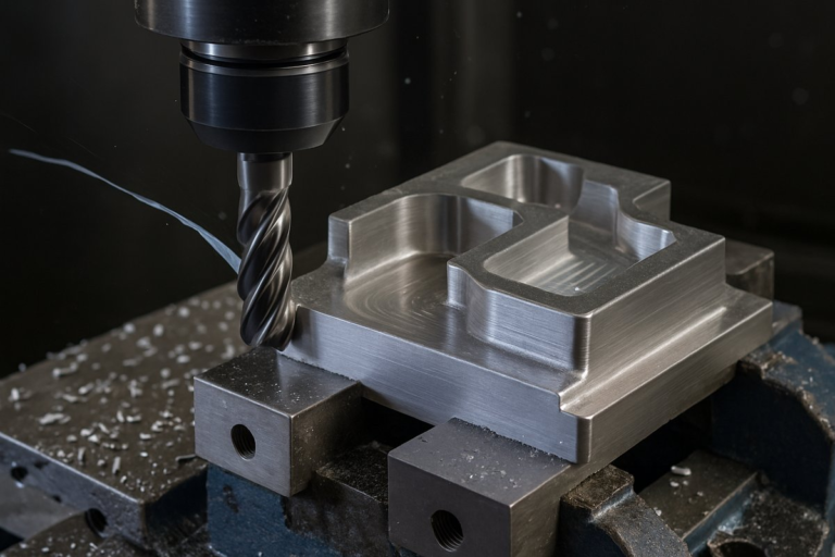
Tool selection makes a dramatic difference. A 6 mm carbide ball-nose end mill is ideal for smoothing contoured surfaces and preserving curves without leaving harsh scallops. For sharp edges, a 4 mm straight flute end mill can trim layers flush with planar faces. Always run coolant or air blast to clear chips and cool the cutter. Dry cutting PLA requires lower spindle speeds-around 12,000-15,000 RPM-while PETG may need a slightly higher air-blast volume to prevent gum buildup.
In your CAM software, import the original 3D model and align it to match the printed part’s orientation on the bed. Generate a roughing pass that removes the bulk of layer echoes with a shallow depth of cut (approximately 0.5 mm) at a conservative feed rate of 1,000 mm/min. Follow with a finishing pass using a smaller step-over-around 20-30 percent of the cutter diameter-to achieve a mirror-like surface. Always simulate the toolpaths to check for collisions and ensure the cutter stays within the material boundaries.
When setting spindle speed and feed, follow the manufacturer’s guidelines for the cutter and material. For PLA, a feed per tooth of 0.03 mm to 0.05 mm strikes a balance between surface quality and machining time. PETG often machines well at slightly slower feeds to avoid heat-related melting. If you have a rigid tapping cycle, resist the urge; finishing plastics works best with conventional milling strategies rather than aggressive adaptive routines.
Run the roughing pass first, watching for any signs of movement or vibration. If the part shifts, pause immediately and clamp more securely. Once the bulk material is gone, swap in your ball-nose mill and switch to the finishing toolpath. Keep an eye on chip evacuation and adjust air blast or vacuum extraction as needed-clogged chips can mar the surface finish in seconds.
After the milling is complete, remove the part and inspect critical dimensions with a digital caliper or micrometer. Check tolerances around holes, slots, and reference surfaces. If minor burrs or tool marks remain, a quick swipe with 320-grit sandpaper followed by a microfiber cloth will restore the shine without altering geometry appreciably.
This hybrid workflow shines in prototyping functional parts like custom enclosures, precise fixtures, and ergonomic grips. It’s also a boon for artistic pieces that blend organic shapes with razor-sharp details. With practice, you’ll develop a library of toolpaths and finishing strategies tailored to each filament type and part geometry.
To optimize your next build, experiment with different nozzle sizes-switch to a 0.2 mm nozzle for intricate features or a 0.8 mm nozzle for faster bulk deposition when final finish will always come from the cutter. Likewise, test various ball-nose radii; a smaller radius yields tighter surface continuity on complex curves, while a larger radius cuts time on gentle contours. Keep detailed notes on speeds, feeds, and depths of cut so your results are reproducible.
By marrying additive and subtractive processes, you’ll transform rough prints into polished masterpieces with dimensional accuracy that rivals traditional machining. The strategy reduces material waste compared to large block milling while boosting precision beyond what raw printing achieves alone. Each component-the nozzle, the end mill, the hold-down system-plays a vital role in elevating your workflow. Embrace this hybrid path, and you’ll find new possibilities for rapid prototyping, custom tooling, and one-off production runs.
Ready to bridge two worlds? Gather your filament, lock in your toolpaths, and fire up your mill. The next time you press “print,” imagine the final cut shaping your vision to perfection.