Location
Mount Vernon, WA 98274
Location
Mount Vernon, WA 98274

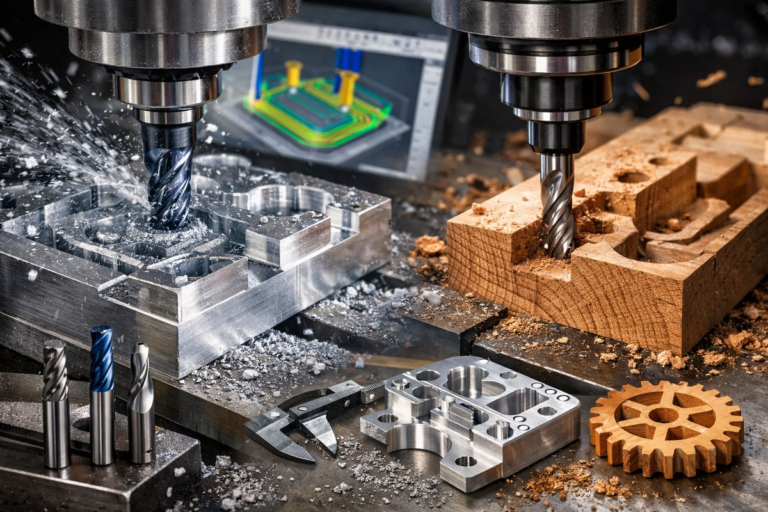
Discover how to integrate desktop FDM 3D printing into your CNC milling setup by creating custom tool holders, quick-change racks, and alignment jigs. This step-by-step guide reviews the fundamentals of filament printing, design strategies, and finishing touches that make your CNC toolbox both nimble and precise.
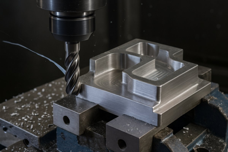
Combining additive and subtractive methods unlocks new levels of flexibility in a machine shop. Rather than relying solely on stock tool holders or off-the-shelf racks, you can design and print custom fixtures that fit your end mills, router bits, and probing heads perfectly. Desktop FDM 3D printing makes this affordable and fast: you sketch a holder in CAD, slice it in minutes, then let the printer lay down material layer by layer. In under an hour you’ll have a bespoke component ready to streamline tool changes and protect your precious cutting edges.
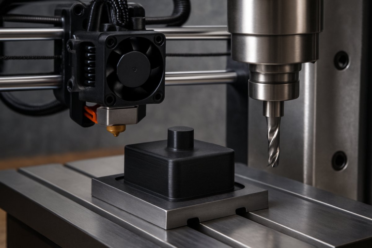
At its core, Fused Deposition Modeling (FDM) melts filament through a heated nozzle, depositing thin beads of plastic that bond as they cool. You choose a build plate temperature and nozzle diameter to match your material-commonly PLA or PETG for tooling prototypes. A slicer translates your CAD model into G-code, setting layer height, infill density, and print speed. By mastering a handful of settings, you can achieve strong, accurate prints that hold tools firmly and stand up to repeated handling in a milling environment.
The design phase starts in your favorite CAD package. Sketch the profile of an end mill shank or router bit and extrude a pocket that matches its diameter plus a small clearance-typically 0.2 mm. Add chamfers at the entry points so tools slide in smoothly, and include small tabs or slots to lock holders onto standard T-slot rails or magnetic plates. You can even integrate labels or numbering embossed onto the surface to ease identification. Parametric modeling makes it simple to adjust dimensions if you swap to different tool sizes later.
Print orientation and support structures have a big impact on final strength and surface quality. For a cylindrical holder, orient the axis vertically so layers wrap around the pocket, reinforcing radial grip. Disable supports inside the bore and use a low layer height-0.15 mm or finer-to achieve a clean finish. A 20 %-30 % grid or gyroid infill pattern balances material use and rigidity. Slow down perimeter speed to around 30 mm/s when printing critical features that contact tool shanks.
Material choice can make the difference between a holder that deforms under torque and one that endures shop handling. PLA is easy to print but soft at elevated temperatures, so it suits low-load fixtures. PETG or ABS resins are tougher and heat-resistant, reducing creep when warm chips or coolant contact the holder. For maximum stiffness, consider nylon blends or carbon-fiber-reinforced filaments. Remember to tune your extrusion temperature and cooling fan settings to obtain reliable layer adhesion without stringing or warping.
Your slicer profile might start with a standard PLA preset, but fine-tuning retraction, coasting, and cooling will yield crisper edges. Increase infill overlap slightly to prevent gaps between walls and infill when you expect radial loads. Add a brim or skirt around the base for small holders to reduce lifting. Many shops benefit from a custom filament profile that raises nozzle temperature by 5 -10 °C for improved layer bonding, then lowers cooling to around 30 % to avoid sudden thermal contraction.
Once the print finishes, remove it from the bed and clear any brim or raft. Lightly sand the interior pocket with fine-grit paper or a flexible deburring tool to eliminate tiny ledges. If you printed in ABS or nylon, consider a vapor-smooth or acetone bath to seal layer lines and increase resistance to cutting fluid. A quick wipe with isopropyl alcohol clears away dust and oils so the holder seats firmly on a magnetic plate or in a T-slot channel without shifting under load.
Let’s look at a practical example: a quick-change end mill rack. Design a base that clamps into a 20 mm T-slot on your CNC table. Model six pockets spaced for 6 mm and 12 mm shank end mills, alternating diameters in a zigzag to save space. Reinforce the bottom wall with ribs under each pocket for rigidity. Print in PETG at 0.2 mm layers and 25 % infill, then press the rack into the rail. Now you can swap tools in seconds without digging through drawers or risking damage.
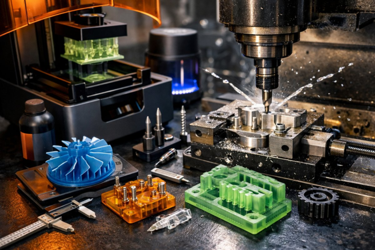
Mounting printed fixtures directly on your CNC table transforms the way you approach short runs and frequent tool changes. Instead of hunting for a collet block, you reach to the rack built into the table profile. No extra hardware is needed: a printed dovetail dovetails perfectly with a milled channel. For router setups you can print spacers and guides that lock onto the spoilboard grid, ensuring consistent alignment when you switch bits or workpieces.
Beyond tool holders, 3D printing powers custom inspection aids. Print a probe bracket that holds an off-the-shelf touch probe at a fixed offset from your spindle. Embed magnets or clips that snap onto standard mill covers, letting you measure workpiece height or alignment without buying expensive proprietary mounts. By controlling the design, you adapt fixtures to your specific spindle nose and probe geometry. This lowers start-up times and reduces error when checking critical dimensions.
To maximize longevity, design tool holders with replaceable wear inserts. Print a robust outer shell in PETG, then glue in small nylon bushings where the shank seats cloud friction zones. If a pocket wears through or loses tolerance after months of use, simply replace the bushing instead of reprinting the entire rack. Incorporate slots that guide snap-in inserts, making maintenance a one-minute operation.
Advanced shops take this further by printing jigs for fixturing odd shapes. For a complex 3D-sculpted part, print a conformal cradle that matches its contours. Clamp the cradle onto a standard T-slot plate, then mill away stock until the part slips free for finishing. This approach minimizes vice marring and supports five-axis operations in a three-axis mill by converting the workpiece into an easy-to-seed shape.
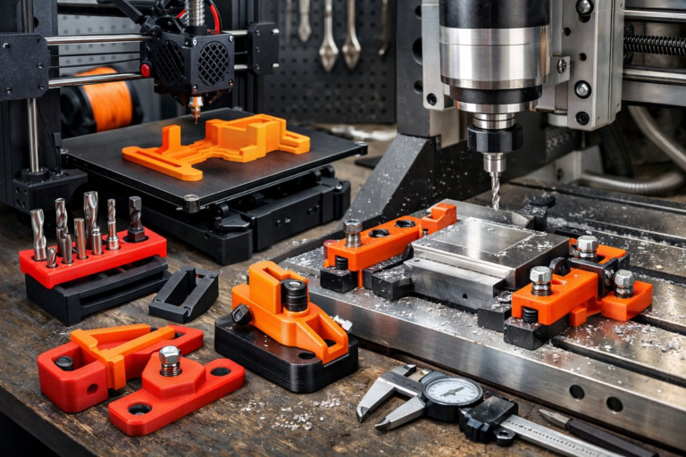
Integrating additive tooling into CNC milling doesn’t require radical investment. A sub-$300 desktop printer yields parts accurate to 0.2 mm, ideal for common end mill tolerances. Once you master a few design and slicing strategies, you unlock rapid prototyping of fixtures and holders that fit your exact workflow. Rather than ordering custom aluminum racks with long lead times, you print what you need today.
Embrace hybrid manufacturing to accelerate setup times and boost shop floor agility. Start by sketching a simple tool rack, iterate the design based on fit tests, and refine your slicer settings until each holder grips tools consistently. As you build confidence, expand into more ambitious fixtures-routing guides, probe clamps, spoilboard inserts-that keep your CNC mill humming with minimal fuss. With a 3D printer at your side, every cutting head has its place, and every minute saved on change-over goes straight to productive milling.