Location
Mount Vernon, WA 98274
Location
Mount Vernon, WA 98274
Discover how FDM additive manufacturing can unlock new levels of precision and flexibility in your CNC routing and milling projects. Learn a detailed workflow for designing, printing, and integrating custom jigs and tool holders-plus tips on filament selection and post-processing to ensure rock-solid performance on the machine.
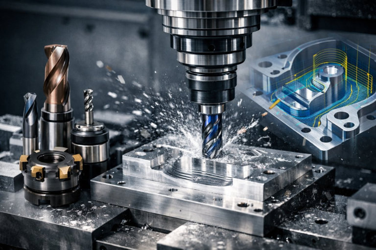
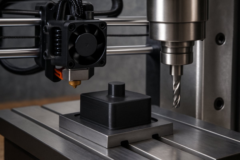
In the world of CNC routing and milling, every fraction of a millimeter matters. Custom fixtures and guides help you maintain consistent cutting paths, reduce setup time, and achieve sharper edges on wood, plastic, and composite materials. By leveraging a desktop FDM 3D printer, you can rapidly prototype clamp-on jigs, end mill holders, and spoilboard adapters that slot perfectly into your workflow. This guide walks you step by step through the process of using FDM printing to fabricate reliable, reusable fixtures that dovetail with your CNC router or mill.
Begin by sketching the basic geometry of the part you want to cut-whether it’s a curved groove, repeated pocket, or edge profile. Open a CAD tool such as Fusion 360 or FreeCAD and model a simple block that matches your stock thickness, adding features like locating pins, dovetail grooves, or a channel for your cutter. Parametric dimensions make it easy to adjust the jig for different tool diameters or material sizes. For example, if you’re routing a 6 mm bit, build in a 6.2 mm hole and a matching collar that slides over the bit shank.
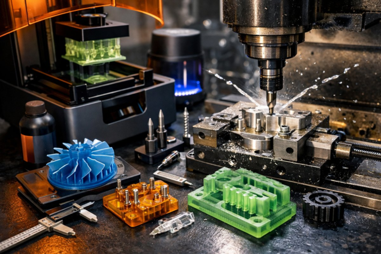
Next, export your jig model as an STL and import it into your slicing software. Choose a filament that balances rigidity with a slight flex-PLA is fine for light-duty guides but PETG or ABS shines under higher cutting forces. Set layer height around 0.2 mm for a good balance of speed and accuracy, and crank infill to at least 50 percent. Walls sliced at 1.2 mm or more will give side loads extra support. Enable supports only where overhangs exceed 60°, and orient the part so fasteners or locating pegs sit flat on the build plate.
Once the slice is complete, print at a nozzle temperature suited to your filament-around 200 °C for PLA, 230 °C for PETG, or 250 °C for ABS. A heated bed at 60 °C for PLA or 90 °C for ABS locks corners in place. Keep your part chamber as draft-free as possible to reduce warping. After the print finishes, remove any support material cleanly with flush cutters. Light sandpaper or a hobby knife can smooth layer lines on mating faces to improve alignment when locking the jig to your spoilboard.
Before mounting to the CNC machine, drill or tap any required threads in the printed part for mounting screws. For heavy loads, insert stainless steel threaded inserts with a soldering iron or epoxy. Secure T-nuts into the spoilboard grid, align the jig over the bit with the spindle raised, and tighten screws just enough to hold. The printed fixture should resist lateral forces without shifting, yet release smoothly when unclamped.
With the jig in place, load your cutting program. Because the fixture raises the work surface, adjust your Z-zero reference accordingly-either by jogging down to touch a scrap piece or by setting a dedicated tool length offset. Slow down initial passes by 10 to 20 percent to account for any slight flex in the printed plastic. Gradually ramp feed rates back up as you confirm the bit path is accurately constrained by your new guide.
Post-cut cleanup is minimal: remove the jig, clear any wood chips from the printed surfaces, and inspect for cracks or wear. High-stress zones like corners of a guide channel may benefit from a coat of thin CA glue or epoxy resin to extend life. If a part fails or you need a new size, simply tweak the CAD parameters and reprint in a fraction of the time it would take to machine a steel fixture.
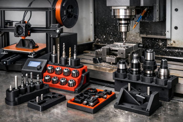
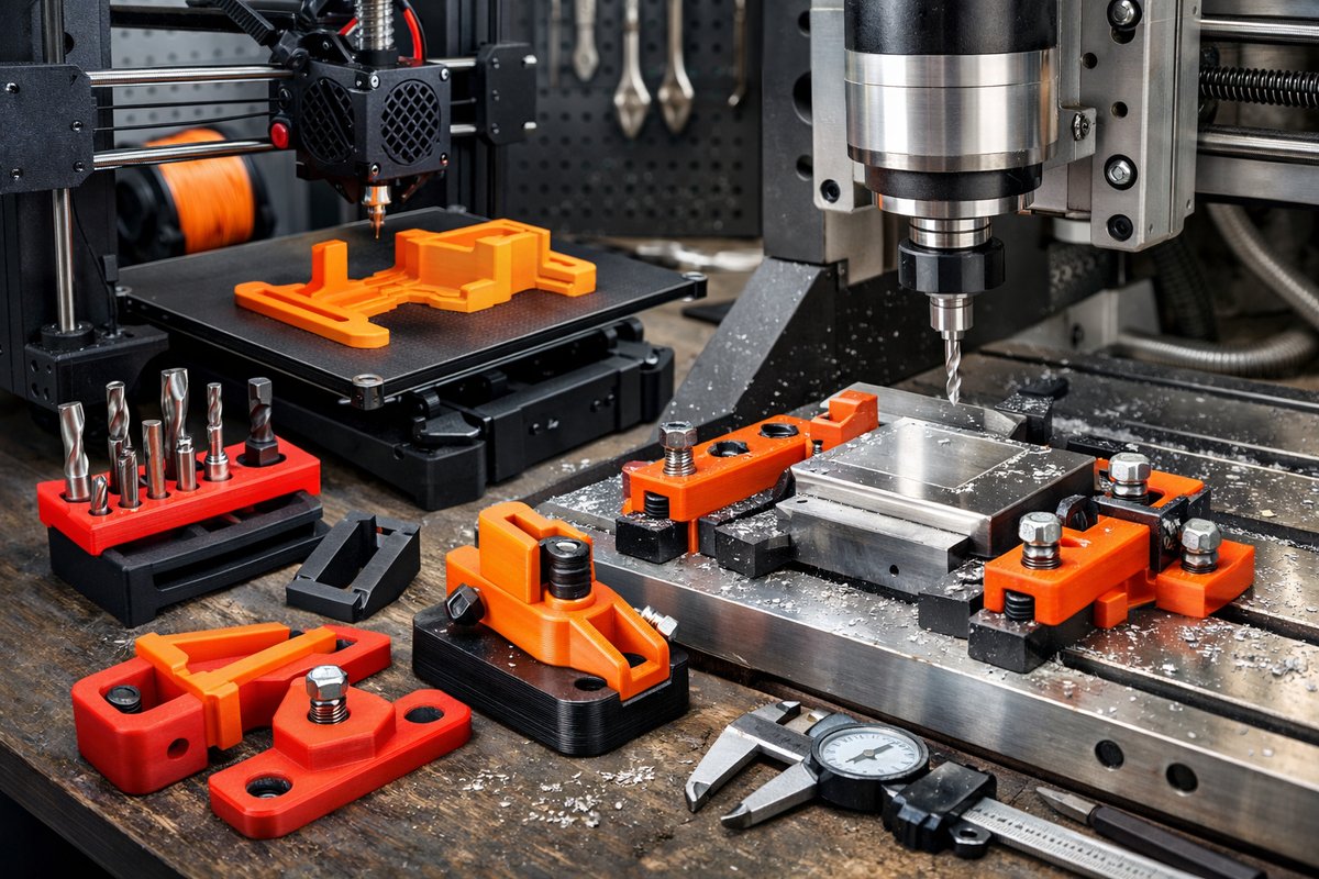
Consider designing multi-purpose fixtures that combine features. A single 3D-printed block can hold two or three bit clamps side by side, reducing changeover time. You might integrate dust collection channels or vacuum cups directly into the print. By nesting tool holders into each other, a storage rack for router bits can live right on your spoilboard, keeping everything in reach.
For CNC mills, the same concept applies. Print end mill holders that slide onto a standard ER-11 or ER-20 collet for quick bit swapping when machining plastics or composites. You can even create novelty tooling like raised embossing patterns by printing a shallow positive relief and using it as a ball-end cutter guide. The only real limit is your CAD skills and filament selection.
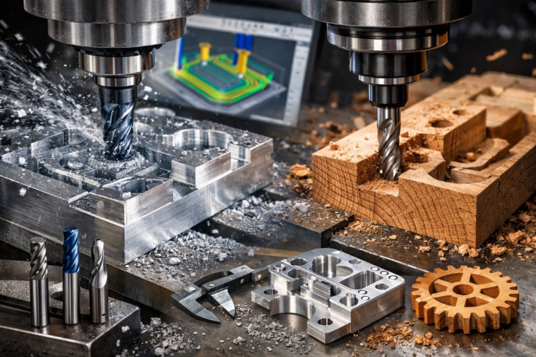
By blending FDM and CNC, you unlock a flexible toolkit: additive makes fast, affordable jigs; subtractive refines precise edges and holes. This hybrid approach accelerates prototyping, reduces wasted material, and expands the range of projects you can tackle. Whether you’re cutting architectural models, crafting intricate wood inlays, or machining functional plastic parts, custom printed fixtures deliver repeatable accuracy without the need for expensive tooling.
Ready to give it a try? Start with a simple router bit guide for a straight slot and build up to multi-feature fixtures as you grow more comfortable. Celebrate each successful cut as proof that additive and subtractive processes belong on the same workbench. The synergy between a 3D printer and a CNC machine isn’t just a trend-it’s the future of highly adaptable, on-demand toolmaking.