Location
Mount Vernon, WA 98274
Location
Mount Vernon, WA 98274
Discover how to elevate your machining projects by exploring high-speed CNC milling methods that deliver both efficiency and pinpoint accuracy. This guide examines a proven milling technique, highlights essential tooling components, and offers practical tips to help you transform raw material into finely finished parts.
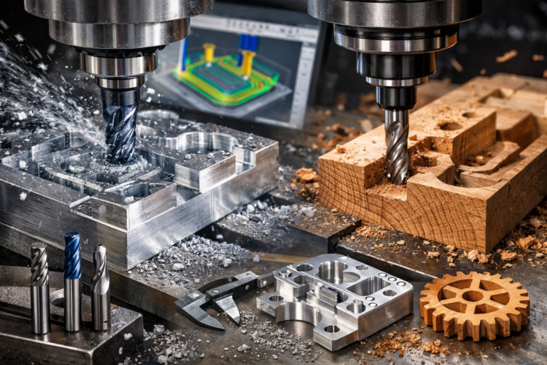
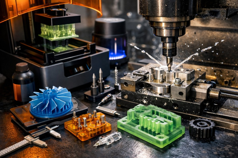
Precision in machining hinges on the interplay between cutting strategy, tooling quality, and machine setup. In this guide, we explore a high-speed CNC milling approach known as adaptive trochoidal roughing. This technique distributes cutting forces more evenly, reduces heat buildup, and prolongs tool life-making it ideal for both aluminum prototypes and hardwood parts. We’ll review the specific steps, tooling choices, and workflow practices you need to achieve consistent, high-quality results, whether you’re outfitting a home-shop CNC router or programming a professional desktop milling center.
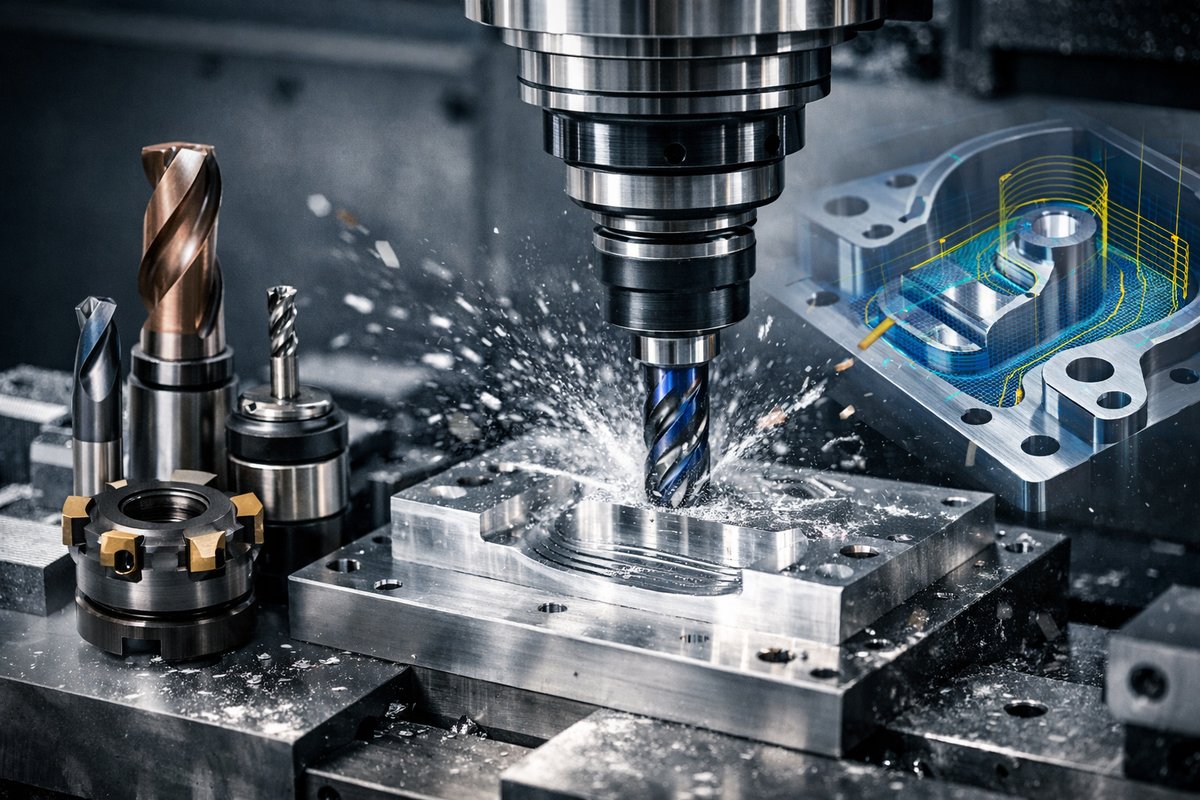
Every successful milling operation starts with the right end mill. For adaptive trochoidal roughing, a carbide end mill with a corner radius or taper performs best. A four-flute, 8 mm diameter end mill with a 0.5 mm corner radius offers a balance between rigidity and chip clearance. The corner radius strengthens the edge, reducing chipping when plunging or ramping into material. With tools like these, you can maintain higher feed rates and deeper cut depths without sacrificing dimensional accuracy.
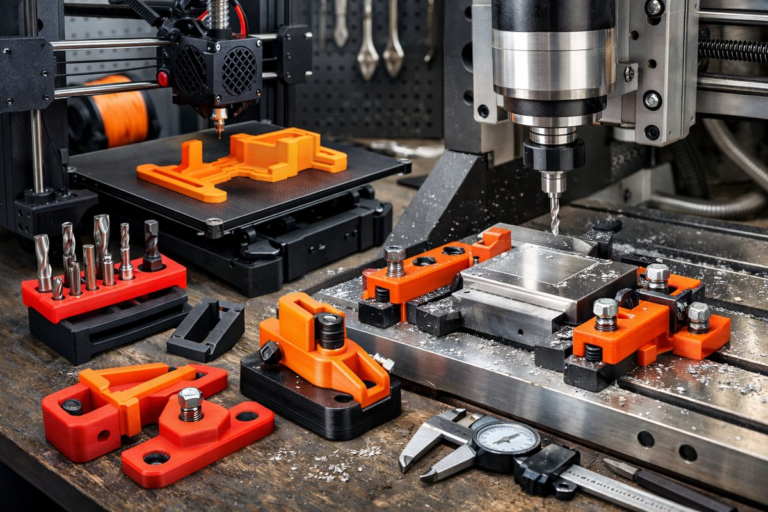
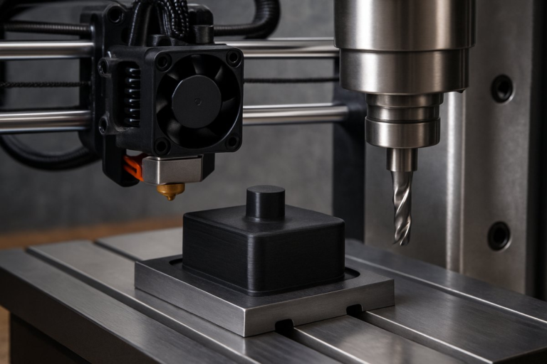
First, secure your workpiece on the CNC machine’s spoilboard or fixture plate. Use dedicated hold-down clamps or a vacuum table if your router supports it. Ensure that the stock is flat and stable to avoid vibration. For metals, you may want to apply a thin film of cutting fluid or mist coolant, although the lighter engagement of adaptive milling often allows dry cuts with efficient chip evacuation. For wood or plastic, compressed air directed at the tool helps clear chips and keeps surfaces clean.
Next, import your CAD model into CAM software. Many popular platforms offer an “adaptive clearing” or “trochoidal milling” toolpath. Set the stepover to around 25-30 percent of the cutter diameter. In our example, an 8 mm mill would use a stepover of about 2.0 mm. This shallow stepover maintains a constant radial engagement, reducing abrupt load changes on the tool. Set your axial depth of cut to 1.5-2 mm for hardwoods, or up to 3.5-4 mm for aluminum alloys, depending on machine rigidity.
A key benefit of adaptive trochoidal milling is its ability to ramp into the material using a helical or linear plunge move rather than a straight plunge. This prevents sudden tool deflection and heat spikes. Configure the entry move to ramp at a shallow angle-typically 1-3 degrees-so the cutter engages gradually. The CAM software will generate smooth, concentric passes that follow the part outline, maintaining even chip load and reducing dwell marks.
With your toolpath generated, double-check the simulation in the CAM environment. Look for potential collision points, uncut areas, or overly rapid direction changes. Adjust feed rates to suit your machine’s spindle speed and torque curve. For an end mill spinning at 18,000 RPM, a feed rate of 1,200 mm/min yields a chip load of about 0.042 mm per tooth on a four-flute cutter. Tweak this value based on your machine’s power and rigidity: more rigid setups can handle increased feed rates, while lighter desktop routers may require slightly slower feeds.
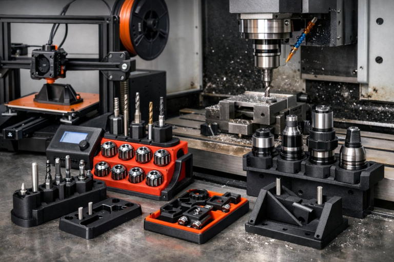
Load the correct collet and tighten the toolholder to the recommended torque. Secure the end mill in the spindle and manually jog the machine to set the X, Y, and Z zero points. If your CNC has a touch probe or an automatic tool setter, use it to speed up the process and ensure repeatable tool offsets. Otherwise, you can establish Z-zero by lowering the tool onto a piece of paper laid on the stock surface until you feel a slight drag.
Initiate the roughing pass and observe the cutter in action through the machine’s window or tablet camera. Listen for a steady but gentle humming sound-if the cutter chatters or you hear a metallic screech, pause the job and reduce the feed rate or depth of cut. Good chip shape is critical: look for thin, curled ribbons in aluminum or fine, uniform shavings in maple or walnut. If the chips are powdery or fused, you’re generating too much heat; cut back by 10-20 percent.
After completing the roughing operation, switch to a finishing end mill. A two-flute or three-flute ball nose cutter with a smaller diameter-say 4 mm-enables crisp detailing around contours and fillets. Set up a parallel finishing toolpath that follows the part geometry with a fine stepover of about 10-15 percent of the cutter diameter. This second pass removes the remaining material and delivers a smooth surface finish. In aluminum, a cutting fluid mist can improve edge quality and wash away chips; for wood, a pre-coated straight flute bit produces cleaner edges and minimal tear-out.
Once milling is complete, inspect the part using calipers, micrometers, or a dial indicator. Compare critical dimensions against your CAD drawing. Small deviations may indicate tool deflection, thermal expansion, or slight workpiece movement. If you notice consistent oversize or undersize results, adjust your tool diameter offset or compensate within the CAM. Remember that tool runout affects precision: high-quality collets and balanced toolholders reduce eccentricity and improve repeatability.
Cleanup and finishing are the final steps to reveal the true beauty of a subtractively machined part. Remove burs with a deburring tool or fine sandpaper, and gently polish surfaces with a Scotch-Brite pad or fine polishing compound. For wood components, a light sanding through 220-grit followed by a finishing oil or wax enhances grain detail. Metal parts might benefit from an anodizing or clear-coat application to prevent oxidation and add visual depth.
Mastering this adaptive milling workflow unlocks several advantages:
– Extended tool life thanks to reduced heat and even cutting forces
– Increased material removal rates compared to traditional pocketing strategies
– Superior surface finishes with minimal secondary handwork
– Consistent dimensional accuracy on both metals and woods
Whether you’re manufacturing precision enclosures out of billet aluminum or crafting detailed wooden inlays, adaptive trochoidal roughing paired with strategic finishing passes offers a powerful combination. By selecting the right end mills, fine-tuning feed and speed parameters, and verifying each step through careful inspection, you’ll build confidence in your setup and achieve repeatable results across projects.
Ready to put these techniques into practice? Start by upgrading your tooling collection and optimizing your machine’s capabilities. Investing in high-quality end mills, reliable workholding, and proper chip management sets the stage for smoother operations and higher throughput. From one hobbyist workshop to another, the quiet hum of a well-tuned CNC router or mill is the sound of ideas taking shape-one precisely carved layer at a time.