Location
Mount Vernon, WA 98274

Location
Mount Vernon, WA 98274
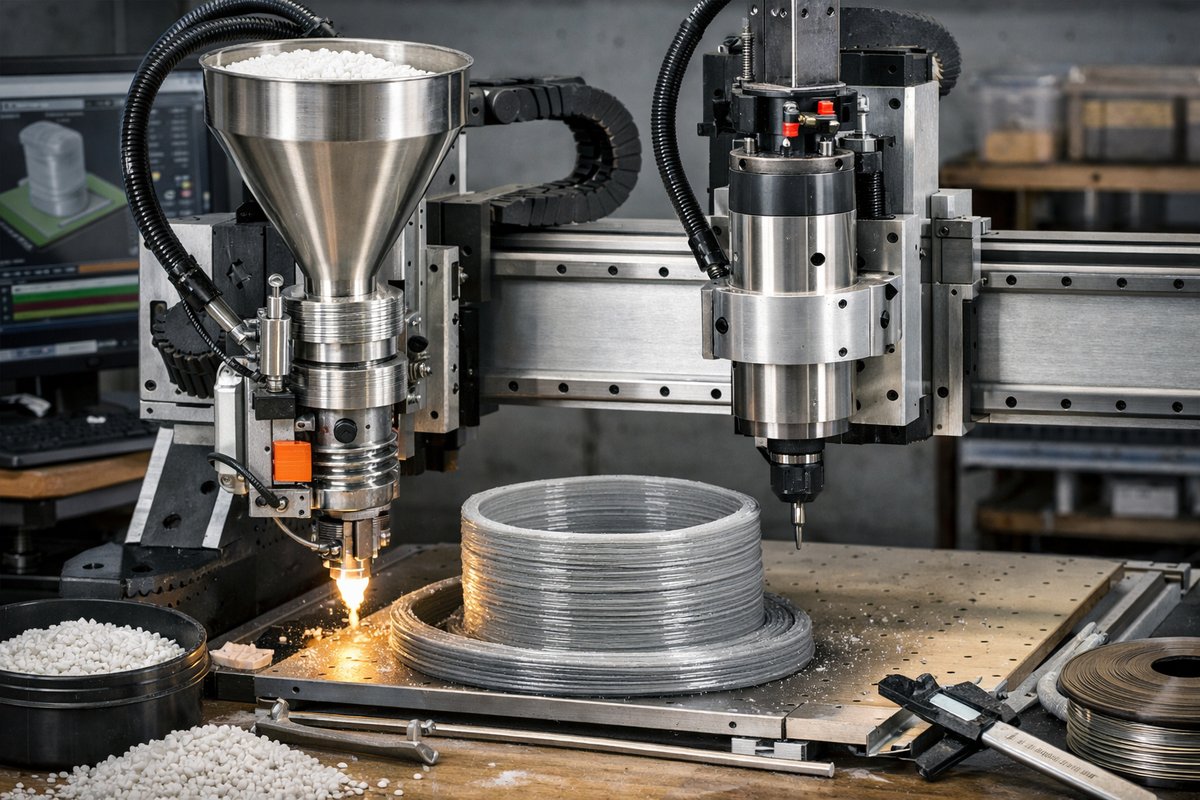
Unlock a new dimension of additive manufacturing by retrofitting a CNC router with a pellet extruder. This method uses inexpensive plastic pellets for faster, sustainable builds and leverages your existing CNC hardware for larger volumes. Follow this detailed guide to assemble, calibrate, and operate a pellet-fed extrusion system alongside precision finishing tools.
Additive manufacturing often conjures visions of standard filament-based 3D printers, yet a growing number of makers are embracing pellet extrusion as a more economical, sustainable alternative. By repurposing a CNC router’s robust gantry and motion system, you can feed raw plastic pellets directly into an extruder module and build large parts at dramatically lower cost. This approach taps into the core strengths of both subtractive and additive workflows: the stiffness and travel of a CNC machine plus the material efficiency and design freedom of extrusion-based printing.
Why Choose Pellet Extrusion on a CNC Router
Plastic pellets can cost as little as one-third the price per kilogram of filament, and they’re available in recycled or specialty engineering-grade formulations. Paired with a CNC router’s high-speed linear rails, pellet extrusion unlocks rapid deposition rates-ideal for large-volume parts or structural prototypes. Once a print is complete, the router’s tooling library, from carbide router bits to ball-nose endmills, lets you finely refine surfaces through light milling passes, blending additive layers into seamless geometry.
Required Components and Tools
To retrofit a CNC router for pellet-based 3D printing, you’ll need:
• Plastic Pellet Extruder Kit with integrated melt zone and hopper
• All-metal hotend assembly rated for 250-300 °C
• Hardened steel nozzle (0.8 mm or larger) to resist abrasion
• NEMA 17 stepper motor with planetary gearbox (for consistent pellet feed)
• Silicone heater pad for the extrusion barrel and a digital temperature controller
• Granule-resistant PTFE tubing or flexible feed hose
• Rigid build surface (PEI-coated spring steel or glass plate)
• Precision 1/4 in carbide CNC router endmill for post-print cleanup
• Wiring harness, limit switches, and a compatible motion controller or expansion board
Preparing Your CNC Router
Start by powering down the machine and locking the gantry in place. Clear any existing tooling and position the build surface at the center of the work area. Mount the pellet extruder carriage using custom brackets or an open-source extrusion mount, ensuring the assembly rides smoothly on the X-axis rails. Lock the stepper motor into place, test for binding, and verify the extruder body remains level throughout the full travel.
Installing and Calibrating the Pellet Extruder
Once the extruder is mechanically secured, attach the silicone heater pad around the barrel and connect the thermocouple to your digital temperature controller. Run a temperature ramp test: heat to 200 °C, wait for stabilization, then monitor for hot spots or temperature drift. Next, calibrate the stepper motor’s steps per millimeter-mark 100 mm of pellet feed, command the extruder to retract that distance, and measure actual displacement. Adjust firmware or controller settings until the extruder consistently moves within ±1 mm of the target.
Setting Up the Slicing Workflow
Pellet extrusion relies on G-code slicers adapted to unconventional extrusion mechanics. Use an open-source tool capable of custom filament profiles-set your layer height to match the nozzle diameter (0.8 mm) and widen the extrusion width to 1.0 mm for overlapping passes. Define a slow first-layer speed of 10 mm/s and ramp up to 30-40 mm/s for subsequent layers. Fine-tune retraction and coasting settings to mitigate oozing; pellet systems benefit from brief back-pressure steps rather than long retractions.
Printing Your First Test Part
Choose a simple geometry-like a hollow cube with 10 mm walls-to validate flow consistency. Home all axes, heat the barrel to the calibrated temperature, and extrude a 20 mm prime line onto the build plate to confirm adhesion. Monitor the initial layers closely: pellets can swell slightly when molten, so you may need to lower nozzle height by 0.1 mm. Once the first layers bond cleanly, let the machine run through the full build. For a 50 × 50 × 50 mm cube, expect roughly 30-45 minutes of print time, depending on your feed rate.
Post-Processing and Surface Finishing
After dismounting the printed piece, remove any stray strings or bumps with needle-nose pliers. To achieve a smooth finish, remount the part on the CNC router and install a 1/4 in carbide ball-nose endmill. Use light stepover passes (0.1 mm) and a shallow depth of cut (0.2 mm) to skim the contours. This hybrid step blends away layer lines without compromising dimensional accuracy, revealing crisp edges and an even surface.
Troubleshooting Tips
Inconsistent extrusion often stems from pellet jams or feed-hose blockages. Check for melted pellets in the hopper throat and ensure the PTFE tubing has no kinks. If you observe under-extrusion, raise barrel temperature by 5 °C increments until flow stabilizes. For over-extrusion or bulging walls, reduce feed rate or widen your extrusion width in the slicer profile. Bed adhesion problems can be solved by adding a thin glue stick layer or switching to a PEI-coated spring steel plate.
With patience and iterative tuning, a CNC-based pellet extruder becomes a workhorse for large-scale prototypes, jigs, or sustainable part production. By combining the low material cost of pellets with the precision of CNC finishing, you open a versatile workflow that bridges subtractive and additive domains-whether you’re a machine shop veteran or a curious maker. Dive into the world of pellet-fed extrusion and discover how subtractive heritage can amplify the creative power of 3D printing.












