Location
Mount Vernon, WA 98274

Location
Mount Vernon, WA 98274
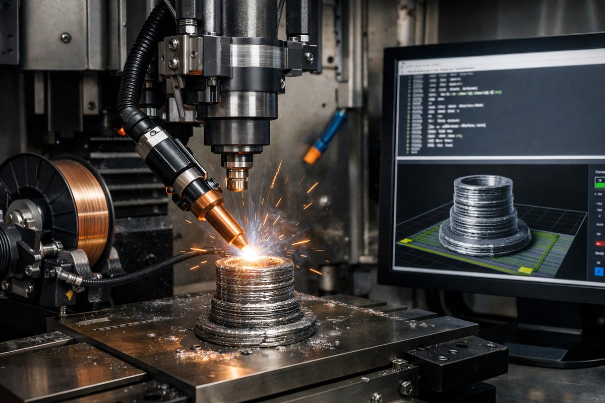
Discover how to transform your CNC mill into a wire arc additive manufacturing system for creating metal parts layer by layer. This guide walks you through selecting components, mounting a welding torch, setting up G-code, and fine-tuning deposition parameters so you can start printing steel directly on your machine.
Subtractive machining has long been the cornerstone of metalworking, but integrating additive techniques like wire arc additive manufacturing (WAAM) opens new possibilities for prototyping, repair work, and complex geometry. By mounting a welding torch and feeding a continuous metal wire, you can use your CNC mill or router gantry to deposit molten metal in precise patterns. Each pass builds up layers that become the rough shape of your part, and afterward you can switch back to end mills and face tools to refine surfaces and achieve tight tolerances.
This article reviews the core components for a DIY WAAM setup, explains how to mount and align a MIG/TIG torch on a gantry machine, and offers best practices for G-code generation, deposition parameters, and finishing techniques. Whether you’re repairing a shaft, fabricating a custom bracket, or experimenting with novel alloys, you’ll gain practical guidance for a successful first build.
Selecting Your Components
A reliable WAAM installation begins with choosing compatible hardware. You need a welding power supply capable of constant current, a wire-feed mechanism, shielding gas, and a robust torch mount. For the machine itself, a rigid gantry with low backlash and adequate travel (at least 300 × 300 × 200 mm) works best. The most critical components include:
• Welding power source: A MIG/MAG machine with adjustable amperage up to 200 A. Look for digital controls and remote voltage sensing.
• Wire feeder: A servo-driven feed unit that can deliver 0.8 mm or 1.2 mm steel wire at speeds between 2 m/min and 12 m/min.
• Torch assembly: A lightweight MIG torch head with interchangeable nozzles and a cooling jacket if you plan long runs.
• Shielding gas system: A dual-gauge regulator for argon-CO₂ mixtures and a flowmeter for fine tuning around 10-15 L/min.
• Torch mount kit: A vibration-damping bracket that clamps to your gantry Z-axis, keeping the torch parallel to the build plane.
Mounting and Calibration
Begin by mounting the torch bracket to the Z-axis carriage. Ensure the torch nozzle sits at a 15°-20° angle relative to vertical to promote smooth metal fluidity during deposition. Use a dial indicator to verify that the nozzle tip remains parallel to the X-axis travel, adjusting shims or bracket bolts as needed. Lock all fasteners with thread locker to prevent loosening under vibration.
Attach the wire feeder to a stable section near your control cabinet, then route the wire through a PTFE liner into the torch handle. Keep the path as straight as possible to avoid feed jams. Connect the feeder motor and wire-in sensor to your CNC control box or to a dedicated welding controller with external start/stop inputs. Calibrate the feed rate by sending manual pulses from the CNC pendant and measuring the actual wire length extruded over fixed intervals.
Establishing G-Code Workflows
Most CAM software focuses on subtractive paths, but you can repurpose its basic toolpath generators for additive work. Define your welding torch as a “virtual mill” with a 0 mm diameter tool. Use contour options to create raster or spiral infill patterns at layer heights between 0.8 mm and 1.2 mm. Export basic G-code and then insert custom M-codes to start and stop the welding arc:
• M100: Enable wire feeder and open shielding gas valve
• M101: Strike arc at programmed voltage/amperage
• M102: Extinguish arc and stop wire feed
Place an M100/M101 pair at the beginning of each contour move, and an M102 at the end. Keep travel moves between passes above Z-safe height to avoid collisions. Many hobby-level CNC controllers allow you to assign these M-codes to output relays, which in turn trigger the welding power supply and gas solenoid.
Tuning Deposition Parameters
Achieving a strong, defect-free layer depends on balancing heat input, wire speed, and travel rate. A typical starting point for mild steel is 140 A at 20 V, with a wire feed of 4 m/min and a travel speed of 150 mm/min. Monitor the bead width-ideally 8-12 mm-and adjust travel speed if the metal piles up or droops.
Watch for common issues:
S-porosity: Increase shielding gas flow or switch to a cleaner argon mix.
S-undercut: Reduce current or slow down travel to allow proper fusion.
S-overbuild: Speed up the gantry or lower the wire feed rate to avoid excessive buildup.
Test on scrap before committing to a final part. Mark cross sections and measure layer heights to confirm consistency. If you see high ridges, you may need to reduce layer thickness to maintain stable geometry.
Design for Additive/Subtractive Hybrid Workflow
One of the biggest advantages of a CNC-based WAAM process is the ability to alternate between deposition and milling without unclamping your workpiece. Plan your part in two stages:
• Additive stage: Generate rough geometry with generous extra material around critical faces. Use your CAM program to leave 2-3 mm of stock for finishing.
• Subtractive stage: Switch back to end mills, face cutters, or chamfer tools. Use in-machine probing to establish zero points on the freshly built surface, then run your finishing toolpaths.
This in situ milling reduces alignment errors and cuts hours from post-build workflows. For complex internal channels, consider designing support structures that you’ll remove with a small ball end mill around critical features.
Post-Build Cleanup and Inspection
After your final pass, let the part cool gradually to avoid thermal stress. Remove any remaining tack welding or support plates, then use a band saw or cutoff wheel to separate the build plate if necessary. Clean the surface with a wire brush or grinder to expose the as-deposited layers.
Inspect under a microscope or use ultrasonic testing if you need to verify bond quality between layers. A handheld laser scanner can capture the 3D profile and compare it to your original CAD file, highlighting any deviations. If all readings are within tolerance, proceed to final polishing or coating.
Safety and Maintenance
Welding on a CNC gantry introduces high heat and UV radiation. Always wear a full-face welding helmet with auto-darkening, flame-resistant clothing, and insulated gloves. Keep fire extinguishers nearby and ensure proper ventilation to remove fumes.
Regularly clean the torch nozzle and tip, replacing liners after every 5-10 kg of wire. Check torch lead connections and gas hoses for leaks. Calibrate your wire feeder monthly to prevent feed rate drift, and verify relay function in your CNC control box to ensure reliable arc control.
Pushing Boundaries with WAAM
Wire arc additive manufacturing on a gantry CNC bridges the gap between traditional machining and modern 3D printing. You can experiment with different wire alloys-stainless steel, aluminum, or even duplex grades-to tailor mechanical properties. Try alternating deposition paths at 90° between layers to build stronger, less anisotropic structures.
Advanced users are exploring thermocouple feedback loops to dynamically modulate arc voltage during each layer, opening the door to real-time heat control and even multi-material builds. With a bit of creativity and careful tuning, your workshop can become a versatile production cell for one-off prototypes and repair jobs alike.
By combining the patience of subtractive machining with the creative freedom of additive layering, you’ll discover new ways to solve design challenges and breathe fresh life into the metalworking craft. Grab your welding gear, tweak your G-code, and get ready to watch your CNC mill transform into a metal printer-one layer at a time.












