Location
Mount Vernon, WA 98274

Location
Mount Vernon, WA 98274
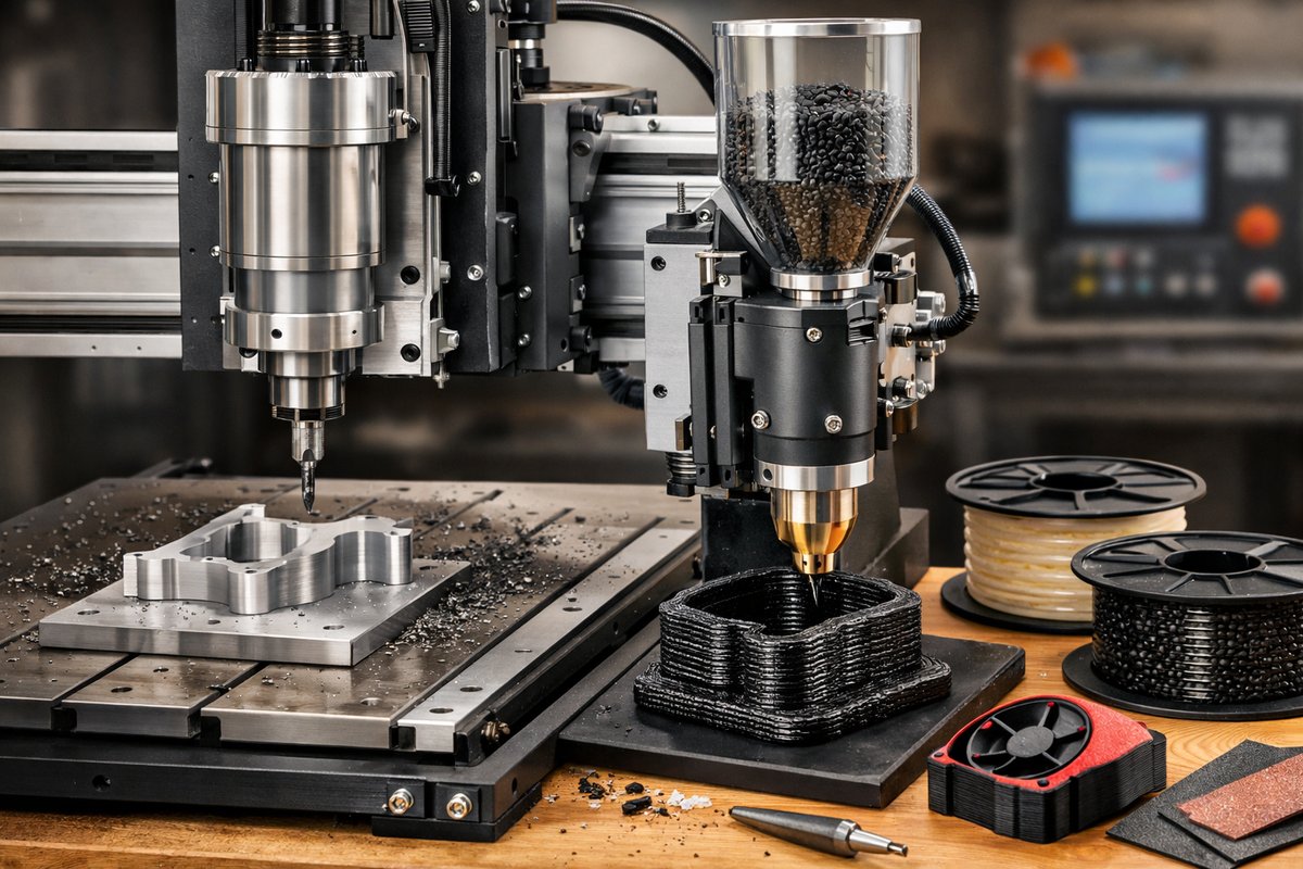
Discover how to transform a standard CNC router into a hybrid additive manufacturing platform using a pellet extrusion attachment. This guide covers machine setup, material selection, calibration, and finishing techniques that blend the precision of subtractive machining with the freedom of pellet-based 3D printing.
Combining the rigidity of CNC routing with the versatility of pellet extrusion opens up an exciting realm of custom fabrication. Rather than layering filament on a desktop printer, pellet extrusion harnesses bulk thermoplastic pellets for faster deposition and lower material cost. Paired with a CNC spindle, you can add material and then precisely mill away imperfections in a single workflow. In this how-to guide, we’ll walk through the steps needed to convert your CNC router, select the right components, calibrate your system, and refine parts with subtractive finishes.
The core of this hybrid approach is a pellet extrusion attachment that mounts to your CNC’s gantry in place of the spindle. This device melts plastic pellets in a heated barrel and pushes the molten material through a nozzle as the machine follows a G-code toolpath. Meanwhile, the CNC router retains its ability to plunge cutter bits for smoothing, trimming seams, and creating fine details that lie beyond the reach of extrusion alone. The result blends the strength and build speed of pellet print with the dimensional accuracy of machining.
Before diving in, gather the following essentials: a CNC router or mill with available Z-axis travel, a pellet extrusion kit engineered for low-shear melting, a heated build platform, a digital temperature controller, standard end mills for finish passes, and a workstation equipped with slicing software that supports volumetric G-code. You’ll also need high-quality thermoplastic pellets-such as nylon, ABS, or polypropylene-chosen based on mechanical requirements and melting point compatibility.
Step 1: Mechanical Mounting and Electrical Hookup. Securely bolt the pellet extruder to the CNC’s carriage plate. Verify that the extrusion barrel clears the machine’s travel limits and that the feed hopper is easily accessible. Route the heater cartridge wiring and thermocouple leads back to the digital temperature controller. Ensure strain relief on all cables to prevent tugging during rapid moves. Grounding is critical; connect the extruder barrel to earth ground to reduce electrical noise that could affect temperature readings.
Step 2: Heated Build Surface Preparation. Unlike filament printers with small beds, pellet extrusion often builds larger blocks. Install a dedicated heated bed or retrofit your CNC table with a silicone heater mat. Cover the surface with a textured sheet or high-temperature tape to improve adhesion. Calibrate bed leveling by jogging the nozzle close to the surface at multiple points and adjusting mount screws until the nozzle barely skims over a feeler gauge. A uniform gap ensures consistent first layers.
Step 3: Material Loading and Prime Filling. Before melting, gently pour pellets into the hopper until it’s about two-thirds full. Activate the heater cartridge to ramp the barrel to the material’s melting point, watching the thermocouple for overshoot. Some pellet extruders include a screw feeder; run it at low RPM until the barrel is fully primed with molten polymer. Slowly extrude a calibration bead by commanding a small G-code move-this flushes out trapped air and confirms nozzle readiness.
Step 4: Slicing and G-Code Generation. Use slicing software that allows you to treat the pellet extruder like a large-nozzle printer. Define nozzle diameter-often 1.5 to 3 millimeters-to balance flow rate and detail. Set layer height to about 60-75 percent of nozzle diameter for reliable interlayer bonding. Configure temperature settings to match your material: for ABS, around 230-250 °C; for nylon, 240-260 °C. Export volumetric G-code adjusted for the extruder’s volumetric flow capabilities.
Step 5: First-Layer Calibration. With the G-code loaded, run a single-layer test. Observe the bead width and height: if it’s too thin, reduce print speed or increase extrusion rate; if too thick, raise the nozzle or decrease flow. Fine-tune the Z-offset until the bead adheres well without excessive squish. A successful first layer lays the foundation for a sturdy, warp-free part.
Step 6: Building the Core Structure. Start printing your model’s infill or bulk sections. Pellet extrusion excels at filling large volumes quickly. Keep an eye on the pellet hopper; replenish before it runs empty to prevent air pockets. Monitor extrusion pressure and adjust feed RPM in real time if you see inconsistent flow. Use slower print speeds for the outer shells to improve surface finish.
Step 7: Transitioning to Finishing Moves. Once the extrusion phase completes, pause the spigot feed and retract the screw feeder. Replace the pellet extruder with a standard end mill-commonly a 4 mm flat-nose cutter or a tapered ball end. Run a finishing G-code toolpath that follows the original model contour. The CNC spindle removes layer stair-steps, sharpens edges, and brings out crisp details in pockets, cutouts, and filleted corners.
Step 8: Post-Machining Cleanup. After milling, the part may have plastic chips and fine dust. Use a soft-bristle brush or compressed air to clear debris. If needed, sand complex areas by hand with progressively finer grit abrasive to smooth micro-ridges. Depending on material, a brief solvent vapor polish can enhance gloss and seal micro-voids. For structural parts, consider an epoxy resin coat to improve surface hardness and chemical resistance.
Step 9: Dimensional Verification. With digital calipers or a 3D scanner, verify critical dimensions against your CAD model. Hybrid additive-subtractive workflows can achieve tolerances around ±0.1 mm on most features. Document any deviations and adjust compensation values in your next G-code to refine accuracy further.
As you gain experience, experiment with different pellets and nozzle sizes. Large-diameter nozzles (3 mm and up) can deliver thick walls and robust infill faster, while smaller nozzles (1.2-1.5 mm) improve surface detail at the expense of print time. Materials like carbon-fiber-reinforced nylon or bio-based polymers open up advanced applications in tooling, fixtures, and prototype casings.
Layer adhesion and print strength also benefit from controlled chamber temperature. If your CNC router is enclosed, use infrared lamps or heated curtains to maintain ambient temperature around 60-80 °C, reducing warping in engineering polymers. Integrated part cooling fans can be toggled on the outer layers for sharper overhangs when printing PLA or brittle blends, though aggressive cooling may harm bonding in high-temperature plastics.
The hybrid process shines in cases where subtractive finish is vital: aerodynamic fairings, structural jigs, custom molds, or ergonomic grips. Bulk sections can be printed thick for strength, then milled thin walls and precise geometric features without sacrificing build speed. For one-off parts or short runs, this approach often beats separate print-then-machine workflows, eliminating the need for fixturing and secondary setups.
This hands-on guide highlights how specific components-the pellet extruder, digital temperature controller, heated bed, and end mills-work together to unlock a new breed of additive manufacturing. You’ve seen how to mount hardware, tune print parameters, switch tools, and polish final parts. The next step is to tailor the setup to your shop: experiment with advanced filaments, customize slicer profiles, and refine your G-code macros.
By embracing hybrid CNC-assisted pellet extrusion, you bridge tradition and innovation. The subtractive discipline of milling meets the additive promise of rapid material deposition. Each layer and each cut reveal more of your original design, transforming raw plastic into purposeful, high-precision components. With patience and calibration, you’ll push the boundaries of what a single machine can do.
Ready to take the plunge? Gather your tools, arrange your workspace for safety and efficiency, and start with a small test block to dial in your settings. Share your successes and challenges with the community-every tweak helps refine best practices for hybrid manufacturing. In time, you might find that this blend of subtraction and addition becomes your favorite way to bring ideas to life.
Equip yourself with these workflows, and you’ll see how additive and subtractive methods can reinforce each other. As resistance meets refinement, and as each pass of the tool uncovers the shape imagined, you’ll appreciate the craftsmanship that thrives where plastic meets cutter, and where layers yield to a final, polished form.












