Location
Mount Vernon, WA 98274

Location
Mount Vernon, WA 98274
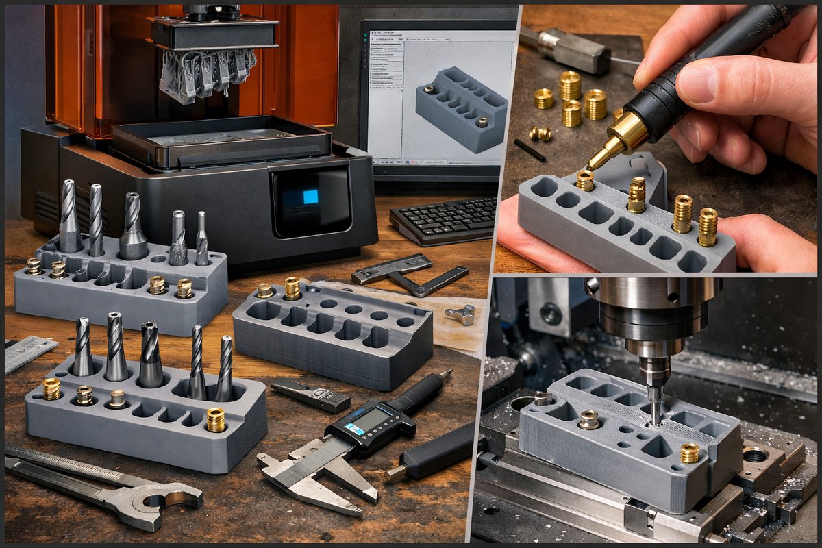
Discover how to harness the accuracy of resin-based 3D printing to fabricate custom tool holders enhanced with heat-set metal inserts, then fine-tune critical dimensions with a CNC mill. This guide walks through every step-from CAD adjustments and printer setup to post-processing, insert installation, and finishing passes on a router or CNC machine-to help you build jigs and fixtures that fit like a glove.
For anyone who spends time at the bench, organizing bits and cutters is more than housekeeping-it’s about having the right tool precisely where you need it. Traditionally, that meant buying pre-made racks or fabricating wooden blocks and drilling holes by eye. But what if you could print the exact form you designed in CAD, embed durable metal threads for repeatable mounting, and then apply a final milling pass to ensure perfect tolerances? Resin-based 3D printing delivers sub-millimeter detail that simplifies layout and alignment, while heat-set metal inserts provide rock-solid anchoring for your router bits, drill heads, or end mills. Add a touch of CNC finishing and you’ll end up with tool holders so accurate they practically index themselves.
Begin by sketching a simple block that matches the shank size of the bits you use most. In your CAD software, model a rectangular prism keeping at least 4 mm of wall thickness around each tool slot. Add small pilot holes or chamfers at the mouth of each slot to guide the bit in. Then draft cavities sized slightly larger than the heat-set insert you plan to use-typically 4 mm deeper than the insert length and 0.2 mm wider all around to accommodate resin shrinkage and thermal expansion during insertion.
Next, orient the part on the printer’s build platform. For a desktop SLA or DLP machine, position the tool holder so the largest flat is parallel to the build plate; this reduces supports and makes post-processing smoother. Tilt the block by five to ten degrees toward one corner to help drains flow and minimize resin traps. Set layer thickness to 50 microns for a great balance of speed and detail. Adjust exposure times according to your resin’s data sheet-often around 7 to 10 seconds per layer for standard 405 nm photopolymer.
Gather needed components: a desktop SLA 3D printer, a fresh vat of clear or gray UV resin, nitrile gloves, safety glasses, and a clean work surface. Don’t forget the support removal tools-flush cutters and plastic scrapers-and a container of 90 percent isopropyl alcohol for washing. While the printer runs, prepare your metal inserts and heating tool. A simple soldering iron with a flat tip, set to about 200 °C, will do the trick of melting resin around the insert for a snug fit.
When the print finishes, lift carefully and detach supports using flush cutters. Rinse the part in alcohol until uncured resin washes clear, then allow it to air-dry for five minutes. Next, place the block in a UV curing station for two to three minutes per side to achieve full hardness. The final resin modulus matters here; a tougher resin (often promoted as engineering or high-toughness grade) resists deformation under heat better than a standard clear resin, so consider resins specified for functional prototyping if you plan frequent insert installations.
With the part cured, heat each metal insert by holding it against the soldering iron tip. Once the metal is hot, press it gently into the matching cavity until it bottoms out. Work quickly but smoothly-too much dwell time can warp the surrounding plastic. Let the assembly cool undisturbed for a minute or two before applying any lateral force. These inserts transform the printed plastic into a stable mounting platform for screws or threaded rods, making your tool holder both modular and long-wearing.
Although the print and insertion process yields a usable part, the final precision comes from a light pass on a CNC mill or router table. Mount the block on the machine bed using double-sided tape or a vacuum fixture. Load a fine carbide flat end mill-1/8 inch or 3 mm diameter works well-and zero the tool at one corner of the largest face. Plan simple toolpaths to skim the top surface by 0.2 mm, and square the sides if needed. This step ensures the block sits perfectly flat in any fixture or drawer you place it in.
If your tool holder has slotted openings that demand tight tolerances, switch to a smaller end mill or a ball nose cutter to relieve sharp edges. Program a pocketing operation at the offset dimensions you designed in CAD. Take light cuts-no more than 0.5 mm per pass-to avoid chattering against the cured resin. The result is an opening that matches bit diameters within a few tenths of a millimeter, guiding each tool into place without wobble or wear.
After milling, deburr any edges and blow off dust with compressed air. Test fit by inserting your router bits, drill bits, or end mills into each slot. The ideal fit should feel snug when you tap the tool gently, then release without sticking. If necessary, adjust the slot width by taking another skim pass or by lightly sanding with fine-grit paper. Keep a digital caliper on hand throughout to verify slot widths and depths-measuring at different points helps catch any minor bowing or unevenness.
Once satisfied with the fit, consider adding labels or identifiers to each slot. You can laser-etch numbers or letters into the cured resin, or embed small magnets and attach magnetic label strips. For a clean look, design tiny recesses in your CAD model that accept printed vinyl stickers or anodized aluminum labels. These finishing touches elevate the holder from a quick prototype to a professional accessory on your workbench.
The true beauty of this workflow lies in its modularity. Need holders for larger cutter heads? Simply scale your CAD block and cavity dimensions, reprint, and repeat. Want a multi-level rack? Stack printed modules and secure them with screws in the embedded inserts. Because you can control every aspect of design-from wall thickness and insert placement to final surface finish-your tool holders become an evolving system that adapts to your collection.
Beyond organizing tools, this process applies to custom mounting plates, jigs for angled cuts, or quick-swap fixtures on your CNC machine. By combining resin printing’s resolution with heat-set inserts’ durability and CNC machining’s accuracy, you unlock a hybrid workflow that maximizes both additive and subtractive strengths. You’re no longer limited to off-the-shelf brackets or slow manual drilling; you’re crafting bespoke solutions that fit your workflow like a glove.
If you’ve been curious about desktop SLA printing but weren’t sure where to start, this project is a perfect introduction. It showcases key steps-slicing, resin handling, curing, insert integration, and CNC finishing-without requiring industrial-scale equipment. And the payoff is immediate: a reliable, customizable tool holder you’ll use every day. With inexpensive materials and straightforward machine setups, you’ll find yourself asking why you ever settled for one-size-fits-all racks.
The next time you need a precise, repeatable fixture, remember that the magic happens at the intersection of technologies. Resin printing lays down geometry with microscopic accuracy, metal inserts ensure mechanical robustness, and CNC milling polishes the result to fit tight tolerances. Embrace this hybrid additive-subtractive approach, and you’ll discover a new level of control over the everyday implements that drive your projects forward.












