Location
Mount Vernon, WA 98274

Location
Mount Vernon, WA 98274
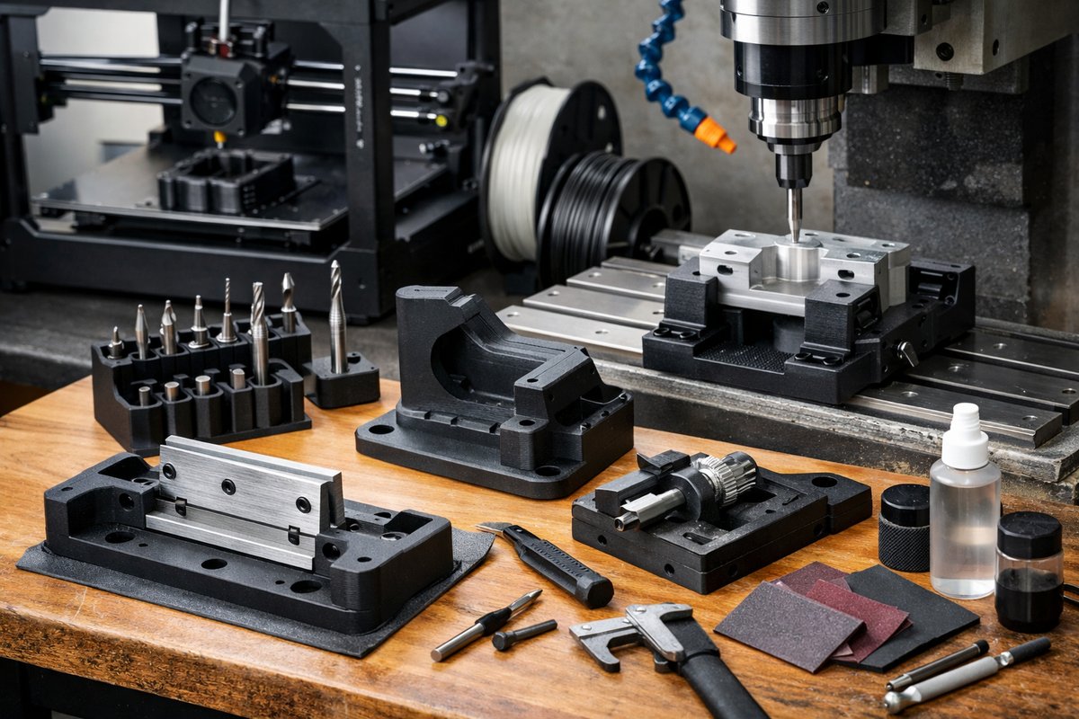
Discover how fused deposition modeling (FDM) can accelerate your subtractive workflow by fabricating custom jigs, tool holders, and fixtures. This step-by-step tutorial reviews best practices-from design and slicing to post-processing-so you can produce durable, high-precision parts that streamline milling and routing setups.
Machining has long been defined by the quiet discipline of cutting away material to reveal an intended form. Today, that tradition meets a new ally: FDM 3D printing. By producing tool jigs, end-mill holders, and alignment fixtures in plastic, you gain flexibility, speed, and cost savings before mounting a block of metal in your CNC mill or routing table. In this hands-on guide, we review the FDM technique tailored specifically for subtractive workflows, highlighting key components, print settings, and integration tips that turn your digital designs into rock-solid shop aids.
Why FDM for CNC Jigs?
FDM excels at rapid prototyping thanks to low material cost and minimal setup time. A tool holder printed in PLA or PETG can be ready in under two hours, compared with days or weeks for machined aluminum prototypes. These printed fixtures are rigid enough to locate workpieces or organize end-mills, and they handle the torque and side loads typical of light-duty milling. When correctly designed and printed, they also resist deformation in a controlled shop environment.
Essential Components and Tools
Designing Your Jig in CAD
Start with a CAD model that integrates mounting points, locating pins, and cutouts for end-mills or workpieces. Plan interfaces so you can clamp the printed part directly to T-slots or mounting holes. Maintain a wall thickness of at least 3 mm around pockets and tool bores-thinner walls invite stress and potential breakage. Add small fillets on inner corners to reduce stress concentration when the jig is tightened under vice pressure.
Slicing for Accuracy
Choose a layer height between 0.12 mm and 0.16 mm for a good balance of surface finish and speed. Set a nozzle temperature aligned with your filament: 200 °C to 210 °C for PLA, 230 °C to 245 °C for PETG. Enable two or three perimeter walls and a 20 percent infill in a grid or cubic pattern for rigidity. Use a brim of five to seven lines to improve base adhesion and prevent warping on the first layer. Disable excessive fan speed: 30 to 50 percent ensures interlayer bonding without undesirable droop on overhangs.
Printing Best Practices
Level your bed carefully, checking all four corners and the center. A consistent nozzle-to-bed gap is critical: too close and filament won’t flow, too far and adhesion fails. Clean the build surface with isopropyl alcohol before each print. If your printer supports a flexible build plate, pop off the completed jig once cool to avoid prying. Inspect the part for delamination or stringing-address these issues in your slicer by adjusting flow rate or retraction settings.
Post-Processing for Shop Ready Accuracy
Remove any brim or raft material with flush cutters or a sharp knife. Lightly sand mating surfaces with 220-grit sandpaper to remove layer lines and ensure crisp edges. If tighter tolerances are required-say, a tool bore that must fit a 6 mm end-mill-drill or ream the hole using a corresponding drill bit or reamer. This hybrid approach combines the speed of FDM with the precision of subtractive finishing.
Mounting and Testing on Your CNC Machine
Secure the printed jig on the machine table using your standard clamps or T-slot hardware. Insert cutting tools into the ER11 collet chuck and seat them into the jig’s pockets. Run a trial pass at low spindle speed (1,000 RPM) and light engagement (0.5 mm depth). Monitor for any movement or flex. If you see deflection, check the clamp torque and reinforce the jig with additional perimeter perimeters in your next print.
Advanced Tips and Variations
Experiment with composite filaments containing fiberglass or carbon fiber for increased stiffness. Switch to a 0.2 mm nozzle and thinner layer heights when surface finish directly impacts part alignment. For jigs that encounter coolant or mild cutting fluids, use PETG or polypropylene blends with higher chemical resistance. You can even print sacrificial sacrificial skim layers on a sacrificial fixture to protect aluminum tables during aggressive pocket clearing.
Troubleshooting Common Challenges
Issue: Warped base on a large jig.
Solution: Increase bed temperature by 5 °C, add more brim lines, or apply a thin layer of glue stick for adhesion.
Issue: Delaminating walls under clamp pressure.
Solution: Raise extrusion temperature by 5 °C, slow print speed by 10 percent, or increase infill to 30 percent.
Issue: Hole tolerances too loose or tight.
Solution: Adjust slicer hole compensation, or plan for a small drilling/reaming operation after printing.
Benefits Beyond the Shop Floor
Beyond jigs and holders, mastering FDM for subtractive workflows cultivates a deeper understanding of material behavior and tight tolerance control. You’ll reduce machine idle time, lower tooling costs, and refine your design-to-production loop. This technique also encourages creative problem solving: once you can print a custom part overnight, complex fixtures become low-risk experiments rather than major investments.
Combining additive and subtractive manufacturing unlocks versatile, agile shop operations. With the guidelines above, you have a proven roadmap to design, print, and integrate high-precision FDM jigs into your CNC milling and routing processes. Grab your CAD files, load your slicer, and see how quickly plastic can pave the way for metal masterpieces.












