Location
Mount Vernon, WA 98274

Location
Mount Vernon, WA 98274
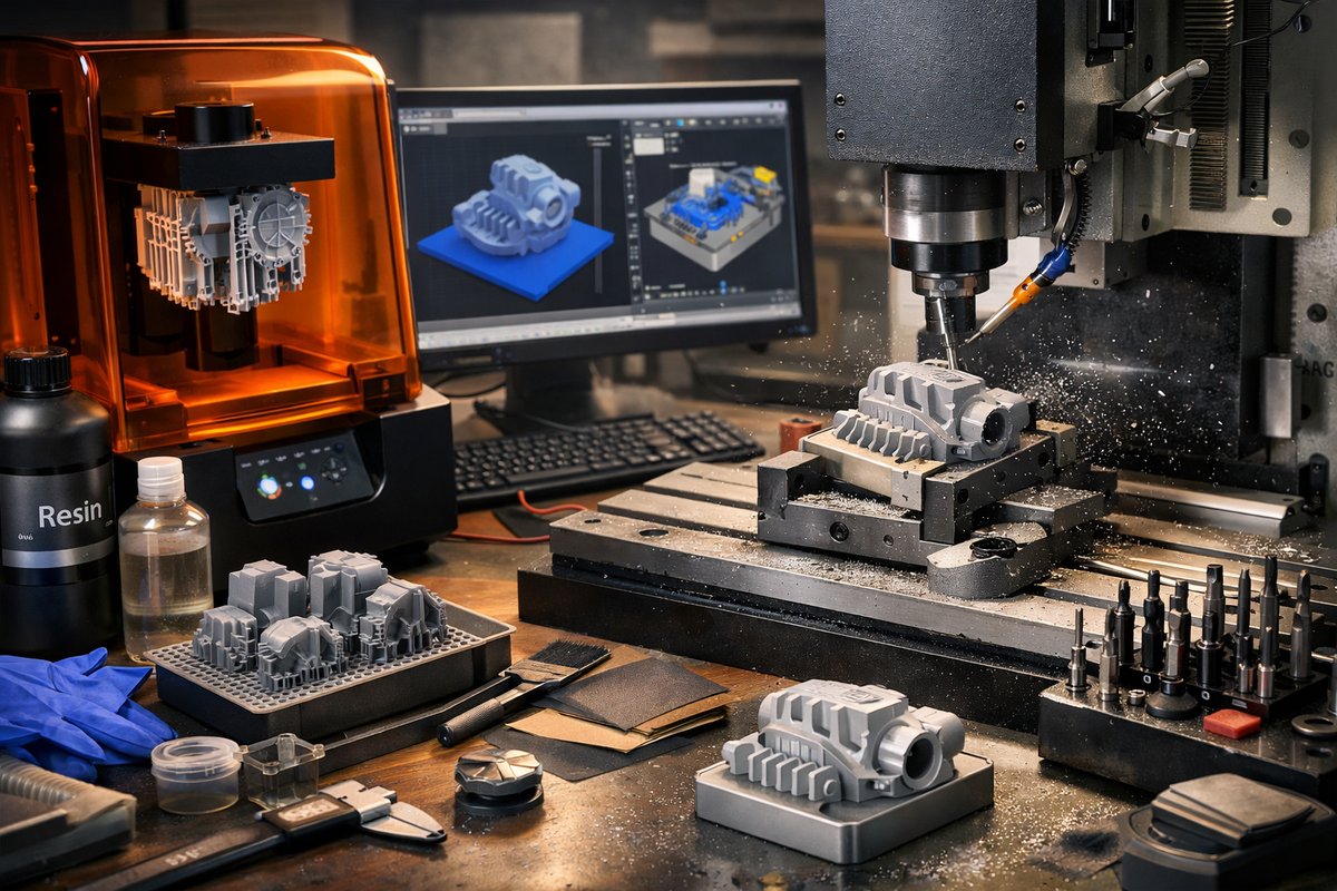
Discover how stereolithography (SLA) 3D printing can be paired with desktop CNC finishing to achieve smooth, precise prototypes straight from your workshop. This step-by-step guide covers resin selection, slicer settings, post-processing, and end mill techniques to refine surfaces and unlock hybrid additive-subtractive workflows.
At the intersection of light-driven polymerization and precise cutting lies a hybrid workflow that transforms digital designs into finely finished parts. Stereolithography (SLA) brings layer heights down to tens of microns, revealing intricate details in resin. Yet even the smoothest print can benefit from the rigidity and repeatability of a CNC router’s diamond-coated end mill. In this guide, you’ll learn how to marry SLA printing with CNC finishing in a desktop setup, turning raw resin prints into polished prototypes, functional jigs, and eye-catching models.
Understanding SLA Basics
SLA relies on a UV laser or LCD array to cure liquid photopolymer resin one thin layer at a time. Unlike filament extrusion, this approach can capture complex geometries and undercuts with extreme precision. Typical layer thickness ranges from 25 to 100 microns, and print accuracy often falls within 0.05 mm on the XY plane. Key components include:
• A resin vat lined with a transparent FEP film that lets UV pass through but keeps the liquid contained.
• A build plate that moves on the Z-axis, lifting each cured layer out of the vat after exposure.
• A laser or UV array that selectively hardens resin according to your sliced data.
Choosing the Right Resin and Components
Resin selection shapes strength, surface finish, and post-cure properties. For workshop prototypes, consider a tough resin designed to resist abrasion during CNC passes. Low-viscosity resins minimize peel forces, preserving fine features on steep overhangs. You’ll also need:
• A replaceable FEP film kit to ensure consistent layer release over multiple prints.
• A sturdy build plate with a textured surface to improve adhesion on the first layers.
• Nitrile gloves and splash-resistant eyewear for safe handling.
Prepping the Print: Slicer Settings and Support Strategies
Proper slicing can reduce post-processing time and improve CNC readiness. When arranging your model in the slicer:
• Orient steep slopes at a 30° angle to distribute peel forces and minimize support size.
• Add tree or lattice supports under overhangs; these detach cleanly, leaving small contact points.
• Set bottom layer exposure higher than normal layers (usually 5-10×) to anchor the print.
• Choose a layer thickness between 50 and 100 microns for a balance of speed and detail.
After exporting the sliced file, send it to the printer, refill the resin vat, and start the job.
Printing and Initial Post-Processing
Once the build plate rises, carefully detach the part using a flat spatula designed for resin prints. Rinse the model in isopropyl alcohol (70-99 %) to dissolve uncured resin from crevices. An ultrasonic wash can improve consistency, but a two-step soak and gentle brush also work. After the IPA bath:
• Let the part air-dry or blow off excess liquid with compressed air.
• Place the dried part in a UV curing station for 5-10 minutes per side, depending on wall thickness.
At this stage, you should see crisp detail but note that the surface may still feel slightly brittle. A full cure strengthens the resin, preparing it for CNC cutting forces.
Preparing for CNC Finishing
Transitioning from a resin print to a CNC-machined object requires stable fixturing and tool selection:
• Workholding: Use a double-sided adhesive plate or a low-profile vise to clamp the part without distortion. Vacuum tables also work if your CNC supports them.
• Tooling: A diamond-coated ball nose end mill in the 1 mm to 3 mm range delivers a fine finish on resin surfaces. For rough passes, a carbide flat end mill can remove bulk material quickly.
• Spindle Speed: Resin cuts cleanly around 15,000 to 18,000 RPM. Lower speeds can cause chipping; higher speeds risk melting the resin.
• Feed Rate: Aim for 500 to 1,000 mm/min on a desktop router. Adjust upward for small-diameter bits to maintain a consistent chip load.
CAM Strategy: From Roughing to Finishing
In your CAM software, import the cured STL and align it to the same coordinate system used for slicing. Then generate toolpaths:
1. Initial Roughing Pass: Use a larger flat end mill (e.g., 3 mm) to remove excess material and flatten the bottom surface or datum area.
2. Parallel Finishing: Switch to the diamond-coated ball nose tool for a contour-parallel pass. Set a scallop height of 0.02 mm for a mirror-like finish.
3. 3D Pencil or Corner Rounding: For sharp internal corners or undercuts left by supports, a pencil-point end mill can refine tight radii.
Each toolpath should avoid over-engagement-keep stepovers under 30 % of tool diameter to maintain surface integrity.
Zeroing and Dry Run
Before the first cutting pass, perform a dry run with the spindle off or at low RPM to confirm clearances. Use a paper feeler gauge to establish Z zero on the resin surface. Verify X and Y coordinates with touch probes or edge finders to align your G-code precisely.
Hybrid Passes and Multi-Stage Workflows
Some advanced users print sacrificial resin fixtures directly onto the build plate. After curing, they machine pockets into the fixture to hold other parts for assembly or testing. This hybrid approach saves setup time and maintains repeatability when producing small batches.
Manual Refinement and Polishing
Even after CNC finishing, a quick hand polish can elevate the part:
• Micro-mesh sanding pads (1,200 to 12,000 grit) can remove minute tool marks.
• A spray buff with automotive polishing compound yields a high-gloss finish.
• Compressed air and detail brushes clear residual dust from fine features.
Common Pitfalls and Troubleshooting
• Warping: If thinner sections warp during curing, add extra supports or lower layer exposure times.
• Chipping: Dull tools or overly aggressive feeds can chip resin. Replace end mills regularly and dial back the feed rate.
• Adhesion Loss: If prints detach mid-job, roughen the build plate or switch to a more aggressive resin adhesive spray.
Why Try Hybrid SLA and CNC?
Combining SLA’s micron-level detail with CNC’s mechanical precision unlocks new possibilities. You can:
• Prototype functional assemblies with snap-fit features and press-fit tolerances.
• Create master molds for silicone casting directly from a 3D-printed pattern.
• Experiment with multi-material builds by machining cavities for insert placement.
The workflow encourages curiosity-iterating quickly from digital model to physical object and back to the computer for refinement.
Next Steps and Exploration
Once you’ve mastered the basics, consider exploring:
• Multi-axis CNCing of printed parts for undercut features.
• Resin blends that include ceramic or metal powders for enhanced heat resistance.
• Automated tool changers to streamline the transition between roughing and finishing tools.
Whether you’re engineering a custom housing, crafting complex jewelry prototypes, or simply honing your shop skills, SLA printing paired with CNC finishing opens a world where light and cutting meet to reveal designs in full relief. Ready your trays, fire up the laser, and let precision shaping elevate your next project.












