Location
Mount Vernon, WA 98274

Location
Mount Vernon, WA 98274
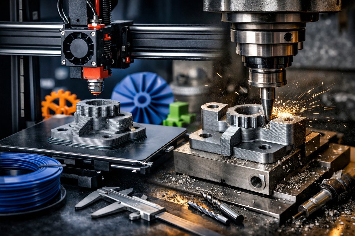
Additive manufacturing, particularly Fused Deposition Modeling (FDM), has revolutionized prototyping and small-batch production by building objects layer by layer. This guide explores the FDM technique in detail and highlights how integrating CNC milling tools can elevate the precision and finish of printed parts, encouraging makers to embrace a hybrid workflow for superior results.
Additive manufacturing (AM) has fundamentally transformed how designers, engineers, and hobbyists approach the creation of complex parts. Among the many AM techniques, Fused Deposition Modeling (FDM) stands out for its accessibility, material versatility, and rapid turnaround. Unlike traditional subtractive methods that remove material to reveal form, FDM builds parts by depositing melted thermoplastic filament layer by layer. This process enables the fabrication of intricate geometries that would be difficult or impossible to machine conventionally.
Despite its strengths, FDM parts often require post-processing to achieve the smooth surfaces and tight tolerances demanded by functional or aesthetic applications. Here, the integration of CNC milling tools-such as end mills and routers-offers a compelling solution. Combining additive and subtractive manufacturing leverages the best of both worlds: the design freedom of 3D printing with the precision and finish of machining.
This article serves as a comprehensive how-to guide for mastering FDM printing and subsequent CNC finishing, focusing on practical techniques, essential tools, and workflow tips to motivate makers to try this hybrid approach themselves.
FDM operates by feeding a thermoplastic filament-commonly PLA, ABS, PETG, or specialty composites-through a heated nozzle that melts and extrudes the material onto a build platform. The nozzle moves in two dimensions to trace each layer’s cross-section, while the build plate lowers incrementally after each pass, allowing successive layers to stack and fuse.
The layer-by-layer nature of FDM allows for rapid prototyping and customization but introduces inherent surface roughness and visible layer lines. Typical layer heights range from 0.1 to 0.3 millimeters, balancing print speed with detail resolution. Warping, stringing, and adhesion issues can also affect print quality, necessitating careful calibration and environmental control.
Successful FDM printing starts with well-optimized 3D models. Designs should consider the limitations of the process, such as overhang angles and support structures. Software slicing tools convert 3D models into machine instructions (G-code), allowing users to adjust parameters like layer height, infill density, print speed, and nozzle temperature.
Choosing the right filament is equally important. PLA is favored for ease of use and minimal warping, while ABS offers greater toughness but requires heated enclosures to prevent cracking. PETG strikes a balance between strength and printability. Specialty filaments infused with carbon fiber or wood particles enable unique finishes but may require hardened nozzles due to abrasiveness.
Maintaining a clean, leveled build plate ensures strong first layers, critical for print success. Utilizing adhesion aids like glue sticks or painter’s tape can prevent warping. Monitoring ambient temperature and humidity helps reduce defects, especially with hygroscopic filaments.
Regular nozzle cleaning and filament storage in dry conditions extend machine longevity and print reliability. Experimenting with print speed and cooling fan settings can fine-tune surface finish and reduce artifacts.
Once the FDM part is printed, CNC milling tools can be employed to refine surfaces, tighten tolerances, and add intricate details. This hybrid workflow is particularly beneficial for functional prototypes, jigs, or molds requiring precise mating surfaces or smooth finishes.
Popular CNC tools for finishing include small-diameter end mills (1-3 mm) for fine detail removal, ball-nose mills for contour smoothing, and engraving bits for text or logos. Routers with variable speed control and rigidity are preferred for handling plastic materials without inducing chatter or melting.
To prepare for CNC finishing, the printed part should be securely fixtured on the milling bed, often using vacuum tables or clamps. Precise alignment is critical; some users employ fiducial markers or probe systems to register the part’s position relative to the CNC coordinate system.
Careful selection of cutting parameters-such as spindle speed, feed rate, and depth of cut-minimizes heat buildup and prevents melting or deformation. Multiple shallow passes are preferred over aggressive cuts to preserve dimensional accuracy and surface integrity.
Consider a scenario where a complex plastic bracket is printed using PLA filament with a 0.2 mm layer height. After printing, visible layer lines and slight dimensional variances exist on mounting holes and mating surfaces.
First, the part is cleaned of any support material and lightly sanded to remove loose strings. Next, it is mounted on a CNC router bed using custom fixtures aligned with the part’s geometry. Using a 2 mm carbide end mill, the critical surfaces are milled to final dimensions, achieving smooth finishes and tight fits. Finally, the part undergoes a gentle polishing step to enhance aesthetics.
This hybrid approach reduces manual post-processing time and yields a part ready for functional testing or assembly.
Combining FDM and CNC milling expands the maker’s toolkit, enabling the creation of parts with complex internal features alongside precision external surfaces. This method reduces reliance on expensive molds or complex machining setups, democratizing manufacturing for small-scale production.
However, practitioners should be mindful of equipment costs, learning curves, and material compatibility. Not all printed materials machine equally well; for example, brittle or highly filled filaments may chip during milling. Proper safety precautions, including dust extraction and protective equipment, are essential when working with CNC tools.
The hybrid additive-subtractive workflow invites curiosity and innovation. Makers are encouraged to experiment with different filament types, print orientations, and milling strategies to discover optimal combinations for their projects. Online communities and open-source software tools offer valuable resources for troubleshooting and inspiration.
Ultimately, mastering FDM printing paired with CNC finishing unlocks new creative possibilities, blending the digital precision of additive manufacturing with the tactile refinement of subtractive techniques. For those willing to invest time and care, the result is a rewarding craft that respects both tradition and technological progress.












