Location
Mount Vernon, WA 98274

Location
Mount Vernon, WA 98274
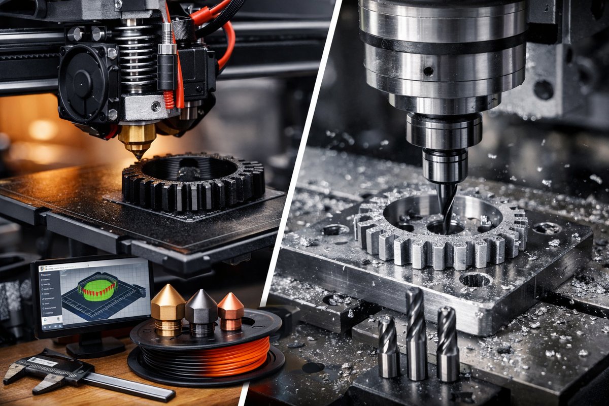
Discover a step-by-step guide to Fused Filament Fabrication (FFF) and learn how to refine printed components with a desktop CNC router for razor-sharp detail. This tutorial explores nozzles, hotends, slicing strategies, and end mills-bridging additive and subtractive manufacturing to unlock professional-grade results.
Additive manufacturing opens doors to rapid prototyping, custom components, and complex geometries that once seemed out of reach. Among its accessible techniques, Fused Filament Fabrication (FFF) stands out for its simple feed-and-melt workflow. While subtractive methods rely on removing material, FFF builds layer upon layer of thermoplastic filament, extruding molten threads that cool into rigid shapes. By pairing FFF with a small desktop CNC router, you can achieve both organic forms and crisp edges in one hybrid process-perfect for parts that demand strength, accuracy, and a polished finish.
At the heart of a reliable FFF setup are a few critical components: the extruder drive, the hotend assembly, the build surface, and the filament itself. The extruder gear must grip filament consistently without slipping, while the hotend nozzle channels melted plastic at controlled temperatures. A silicone build surface or glass plate coated with a removable adhesive film helps parts adhere during printing and release cleanly afterward. A part-cooling fan shapes overhangs and bridges by solidifying each strand as it lays down.
Nozzle selection greatly influences print quality. A standard brass nozzle with a 0.4 mm orifice delivers reliable performance for most PLA workloads, but abrasive or composite filaments call for a hardened steel nozzle or even a ruby-tipped variant. An all-metal hotend kit with a stainless steel heat break resists clogging when you push temperatures above 240 °C-ideal for PETG, ABS, or specialty materials. Keep extra silicone-coated build mats on hand to swap out quickly between different filaments and adhesive profiles.
Before ever sending G-code to the printer, calibrate your Z-axis offset and bed level. A digital dial indicator or precision digital caliper ensures that the first layer lays down at exactly the right height. A common technique is the paper-sheet test: slide a piece of printer paper between nozzle and bed and adjust until you feel slight friction. Consistent first layers make all the difference in preventing warping or shifts, especially when the part is large or uses stiff filaments.
With hardware tuned, turn to slicing software. Set your layer height to half your nozzle diameter-so for a 0.4 mm nozzle, use 0.2 mm layers-to balance speed and detail. Infill patterns like gyroid or honeycomb provide strength with less material. If your design includes overhangs beyond 45°, enable support structures: either breakaway supports printed from the same material or water-soluble supports printed with a PVA extruder. For dual-extrusion workflows, swap to a dedicated PVA filament in one drive gear and calibrate the purge tower to avoid cross-contamination.
When using water-soluble supports, tune printing temperatures for each material. PLA sections might print best at 200 °C with 60 °C bed, while PVA sections need 215 °C nozzle and 50 °C bed. Keep your build chamber humidity below 30 percent by storing the PVA spool in airtight containers with desiccant packs. After printing, immerse the model in warm water for a few hours to dissolve supports, then rinse and air-dry. The result is a clean surface ready for further finishing.
For many prototypes the print quality is enough as-is, but industrial designers and engineers often demand tighter tolerances and smoother facets. That’s where a desktop CNC router comes in. Mount your printed part in a simple vacuum fixture or use double-sided tape on an aluminum fixture plate. Load a 1/8 inch carbide end mill or a 1 mm ball-nose cutter in the spindle. Set conservative feed rates-around 200 mm/min at 10,000 RPM-to gently skim the outer layers without tearing the plastic.
The CNC finishing pass can remove layer lines, refine mounting holes, or carve precise channels. In one test, a printed gear with 0.3 mm layer lines was finished with a 0.5 mm ball end mill run at a DOC (depth of cut) of 0.1 mm per pass. The result: tooth profiles accurate within 0.05 mm, eliminating backlash in a custom linkage assembly. A lightweight vacuum shoe attached to the router cleared swarf and plastic chips, keeping the work area clean and the part visible as it routes.
Bridging additive and subtractive in a single workflow lets you tackle designs that would be impossible by either technique alone. Think conformal cooling channels inside cast resin molds, then CNC series-drill precise holes for alignment pins. Or print an ergonomic handle and carve in toolmarks or logos with a fine-tip engraving mill. By planning your CAD model with both toolpaths in mind-reserving flat planes for CNC passes and support-free ceilings for printing-you can optimize fixture points and avoid collisions between router bits and printed geometry.
Every process has its quirks. Stringing between islands often indicates that retraction settings need tuning: try increasing retraction distance by 1 mm or raising retraction speed to 40 mm/s. If layer shifts appear, inspect pulley tension and tighten the X-axis belt. On the CNC side, chatter marks mean either too aggressive a feed rate or insufficient spindle speed; dial your feed per tooth down to 0.02 mm/tooth for small cutters. Use a handheld digital micrometer to measure critical dimensions before and after each finishing pass to track accuracy.
Material choice makes a big difference in final properties. PLA is easy to print and fine for aesthetic models, but it softens above 60 °C. For functional prototypes exposed to heat or moisture, consider PETG or ASA filaments. Carbon-fiber-reinforced nylon combines toughness with rigidity-though it wears down brass nozzles quickly. Always store filaments in low-humidity environments, and feed abrasive blends through steel orifice nozzles to avoid clogging.
By mastering FFF and coupling it with precision CNC routing, you gain the best of both worlds: organic, lightweight structures from additive layering alongside razor-sharp details from subtractive cutting. This hybrid approach accelerates prototyping, cuts tooling costs, and gives makers the freedom to iterate rapidly. Gather your printer, hotend upgrades, slicing profiles, milling bits, and fixtures-then set aside a weekend to experiment with your own workflow. With practice, you’ll be able to transition from digital sketch to ready-to-test part in just a few hours.












