Location
Mount Vernon, WA 98274

Location
Mount Vernon, WA 98274
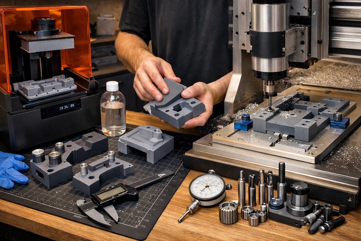
Discover a step-by-step guide to harnessing desktop SLA 3D printing for custom machining jigs and surface fixtures. Learn how to design, print, post-process, and then finish your parts on a CNC router using key tooling components for tight tolerances and professional results.
In a traditional machine shop, precision jigs and fixtures are at the heart of every repeatable setup. But what if you could skip the time-consuming process of hand-milling complex contours or carving folded angles out of billet? By combining desktop SLA 3D printing with a CNC router, you can produce high-detail workholding accessories with minimal lead time. This guide walks through an additive-then-subtractive workflow focused on resin printing of custom jigs, followed by CNC finishing using end mills and routing bits. The result is durable, accurate fixtures ready for production or prototype runs.
The magic starts with additive manufacturing. Unlike FDM technology, SLA printing cures liquid resin layer by layer with a UV light source, yielding exceptionally smooth surfaces and sharp detail. That surface quality reduces the amount of stock you need to remove on the CNC and ensures tight tolerances right out of the vat. Resin jigs can include pocketed recesses to locate stock, angled faces for clamping, and custom nesting cavities that would be difficult or time-intensive to mill from solid plastic or aluminum.
First, design your jig in CAD. Start by determining the mounting interface between the jig and spoilboard or T-slot table on your CNC router. Include locating pins or dowel holes to index the part in the same position every cycle. Build in 0.1-0.2 mm of draft on vertical walls to facilitate resin peel forces during printing. If your router table has 20-millimeter T-slots, add matching T-nut recesses. When dimensioning pockets for raw stock, account for both the nominal thickness of your workpiece and any slight shrinkage of the resin.
Next, orient the model in your slicer for SLA printing. Lay flat faces parallel to the build plate when possible, so each layer has ample cross-sectional area. Avoid long, unsupported overhangs without supports. Place support structures on non-critical surfaces or in filleted regions that can be sanded away later. Set layer height to 50 microns for a smooth finish, or 100 microns if speed is more important than top-surface polish. Fine tuning support density will reduce post-cure cleanup time.
Before pressing print, choose a resin formulated for mechanical strength rather than pure presentation. Tough resins or engineering-grade blends resist cracking under clamp pressure and repeated use. Inspect the FEP resin vat film for any nicks or buckles that could distort layers. Ensure the build plate is level and clean. Pour filtered resin into the tank, then run your standard pre-print routines: tilt the plate away, lower to contact the resin, and confirm a uniform first-layer exposure.
When the print finishes, transfer the build plate to a rinse station. Agitate the parts in isopropyl alcohol or a specialized solvent until uncured resin washes away. Use soft brushes or gentle spray nozzles to clean pockets and recesses. Once clean, remove the supports with flush cutters and trim any whiskers from attachment points. Then move into a UV curing chamber set at the recommended wavelength for your resin. Rotate the part every few minutes so that light reaches all surfaces evenly.
With the printed jig fully cured, it’s time for CNC finishing. Mount a spoilboard or wasteboard on your router table and clamp it flat. If you plan to use T-slot clamps, install T-nuts ahead of time. Position the jig on the table using the built-in locating features you designed in CAD. Add a tiny bead of double-sided foam tape under low-contact areas to prevent any flex during initial tool engagement.
Choose your tooling carefully. A 1∕4-inch flat end mill makes an excellent roughing tool for trimming bulk resin and squaring up faces. Follow with a 1∕8-inch ball-nose carbide end mill to refine radii and smooth curved transition zones. If you need to machine smaller channels or detail pockets, use a micro end mill such as a 0.8-millimeter tip. Always check that your collet or tool holder is clean and that the bit is seated all the way in the chuck before tightening.
Build a simple two-step toolpath in your CAM software: roughing and finishing. For the roughing pass, set feed rates around 600 mm per minute and spindle speeds near 12,000 rpm. Keep the depth per pass shallow, around 0.5 mm, to avoid putting too much stress on printed features. For finishing, slow down the feed to roughly 300 mm per minute with a shallower 0.2-millimeter depth of cut. The ball-nose end mill will produce an even surface ready for inspection.
Before running the full toolpath, jog the spindle to each tool change position to verify clearance. Engage the first tool and zero all axes on a nearby corner of the jig. Run a single air-cut pass to ensure your toolpaths stay within expected bounds. If everything looks good, start the roughing cycle and watch carefully to catch any unexpected flex or chatter. After roughing, retract the tool and switch to the ball-nose bit for finishing.
Once the finishing pass is complete, unclamp the jig and clean any residual dust or chips. Check critical dimensions with calipers or a dial indicator. Verify hole centers, pocket depths, and face flatness against your design. A slight adjustment to finish offsets in the CAM table may be necessary if you notice consistent deviation across multiple features. It often takes just a few tenths of a millimeter of tweak to dial in perfect accuracy.
The result is a high-precision fixture that will locate stock repeatably and clamp securely in place. Custom reactive jaws, vacuum manifold plates, or part trays can all spring from this same workflow. Should you need a quick revision, go back to your CAD file, make changes, reprint the jig, post-process, and finish on the CNC again. An afternoon investment gets you closer to zero-waste setups and fewer manual layout operations.
Beyond speed, this hybrid strategy encourages experimentation. Try integrating channels for pressurized air to blow chips clear of the cutter. Slot in magnets to hold steel parts. Carve dovetail tracks into the printed body for sliding stops. The only real limit is your imagination in CAD and the capabilities of your router’s travel and tooling selection.
From a sustainability perspective, additive jigs can reduce scrap compared to machining from large blocks of plastic or wood. Many SLA resins offer recyclability or reusable scraps. When machines finish the final touches with minimal removal, tooling life increases and energy consumption drops compared to full-size milling jobs.
This modular process can be scaled to small desk-top routers or full-size industrial machining centers. It bridges the world of subtractive discipline and subtractive creativity by letting additive manufacturing shape the initial form. As you grow comfortable, you might explore multi-axis approaches or even 5-axis trimming of complex freeform surfaces.
Whether you’re a curious hobbyist, a novice shop administrator, or a seasoned machinist, blending SLA printing and CNC finishing unlocks new workflows. Embrace the quiet discipline of machining with the boundless flexibility of resin printing. The pattern revealed through subtraction may begin with light, but it shines brightest when paired with the precision cut of a rotating tool.












