Location
Mount Vernon, WA 98274

Location
Mount Vernon, WA 98274
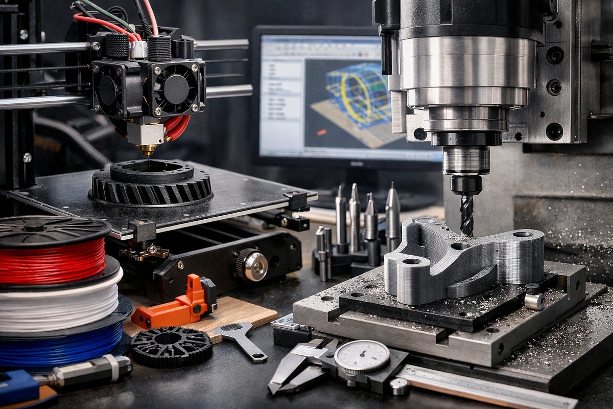
Discover how fused deposition modeling (FDM) 3D printing can open new doors for precision parts and prototypes when paired with a CNC router for finishing. This guide dives into selecting the right nozzle, filament, slicing settings, and post-print milling tools to refine details, boost accuracy, and bring your designs to life.
Additive manufacturing has transformed the way we approach design and fabrication, turning digital models into tangible objects layer by layer. Among the various additive techniques, fused deposition modeling (FDM) remains one of the most accessible, affordable, and versatile options for makers, hobbyists, and professionals alike. But even the most careful print can benefit from a touch of traditional machining. By combining FDM with CNC finishing, you can sharpen edges, refine features, and achieve tolerances that elevate your printed parts beyond the usual limitations of plastic layering.
At its core, FDM printing relies on a heated nozzle that extrudes molten thermoplastic-commonly PLA, ABS, or PETG-onto a build platform. The printer follows toolpaths generated by slicing software, depositing each layer in precise increments, often between 0.1 mm and 0.3 mm thick. A sturdy frame, reliable motion controllers, and a temperature-controlled bed ensure dimensional stability. Beyond the printer itself, key components include a hardened nozzle for handling abrasive filaments, a flexible build plate surface for easy part removal, a spool holder that minimizes drag, and a filament dryer to maintain low moisture levels.
Step one is preparation: start in your CAD environment, refining geometry for both printability and subsequent milling. Consider adding chamfers or draft angles to features that will undergo CNC finishing. Export your model in STL format and import it into slicing software. Here, choose a nozzle diameter that balances speed and detail-0.4 mm nozzles are a go-to, while 0.25 mm or 0.6 mm options can deliver finer or faster results respectively. Adjust layer height to about 60-80% of your nozzle diameter to ensure proper interlayer adhesion and surface quality.
Slicing parameters have a profound impact on both print speed and final strength. A 20-30% infill provides structural rigidity for most prototypes, while 100% infill can be reserved for parts under heavy mechanical stress. Walls or perimeters at two to three passes yield a solid shell. Enable supports only where necessary-overhangs above 60° typically require scaffolding. Use a brim or raft to improve adhesion on the first layers, and maintain bed temperature at 50-60 °C for PLA or 90-100 °C for ABS. Keep your print environment enclosed to mitigate warping and improve layer consistency.
Once the print is complete, let it cool fully before removal. Gently flex the build plate or use a thin spatula to release the part, taking care not to gouge the surface. If you’ve used a flexible plate, it will pop prints off with a simple bend. Examine the model for layer lines, stringing, or minor blemishes. A quick trip to the side with a set of needle files or fine-grit sandpaper (220-400 grit) helps remove small artifacts before milling.
For post-print detailing, mount your part on a CNC router. Secure it to a spoil board using low-profile clamps or double-sided tape. Zero your axes, making sure the spindle is square to the workplane. Select a 1/8-inch carbide end mill-ball-nose bits excel at rounding corners and preserving curved surfaces, while flat-end mills will level and sharpen planar faces. Rigidity is critical: keep spindle speeds at 12,000-18,000 RPM and feed rates around 80-150 in/min, tuning the numbers according to the bit geometry and material hardness.
Begin with a light roughing pass, removing 0.5-1 mm of excess material around the perimeter. This isolates the high-resolution features from the printed scaffold and allows the precise bit to approach only the areas that need fine detail. Once the rough cut is complete, switch to a finishing strategy using a shallow pass of 0.2-0.5 mm. The goal is to skim off layer lines and reveal the crisp edges and smooth planes you envisioned in CAD.
Calibrate your setup with digital calipers and a dial indicator before each session. Measure the nozzle offset, bed flatness, and bit length to ensure consistent results. Regularly check end mill wear; a slightly dulled cutter can introduce chatter and oversize your parts. Replace or sharpen bits whenever you notice excessive burr buildup or inconsistent finishes.
Adhesive bonding and inserts bring another layer of functionality. For assemblies, press-fit brass threaded inserts into printed bosses or use cyanoacrylate glue to bond parts with complementary surfaces. CNC-milled pockets can add recesses for fasteners, magnets, or decorative inlays. By mixing additive shapes with subtractive cavities, you gain the best of both worlds: organic geometry from printing and sharp features from milling.
Environmental factors also play a role in print-to-mill workflows. Keep your filament in a sealed container with desiccant to prevent moisture absorption, which can lead to bubbles and poor layer adhesion. A dedicated filament dryer set at 50 °C for two to four hours will restore brittle or noisy feeds. Maintain ambient temperature and humidity to reduce warping, especially when working with hygroscopic materials like nylon or PETG.
Safety should never be overlooked. Wear protective eyewear and a dust mask when sanding or milling. The fine plastic dust that escapes during finishing can irritate lungs and settle on electronic components. Use a shop vacuum or dust collection system at your CNC machine’s dust port to keep your workspace clean and your lungs happy.
Finally, embrace iteration. Each part you print and mill teaches you more about machine tolerances, material behavior, and design for manufacture. Keep a logbook of feed rates, spindle speeds, and slicing tweaks. Note how PLA compares to ABS or PETG in terms of finish quality, strength, and ease of milling. Over time, you’ll build a library of profiles and toolpaths that let you move seamlessly from digital sketch to precision object.
By bridging the additive and subtractive domains, you unlock a richer palette of creative possibilities. No longer limited by layer heights or the stepover of a mill alone, you can achieve hybrid components that are as functional as they are beautiful. Whether you’re prototyping enclosures, crafting functional jigs, or sculpting one-off art pieces, FDM printing paired with CNC finishing offers a hands-on route to innovation. Gather your printer, router, the right end mill, and a healthy dose of curiosity-and discover how subtraction can sharpen the once-layered world of printed parts.












