Location
Mount Vernon, WA 98274

Location
Mount Vernon, WA 98274
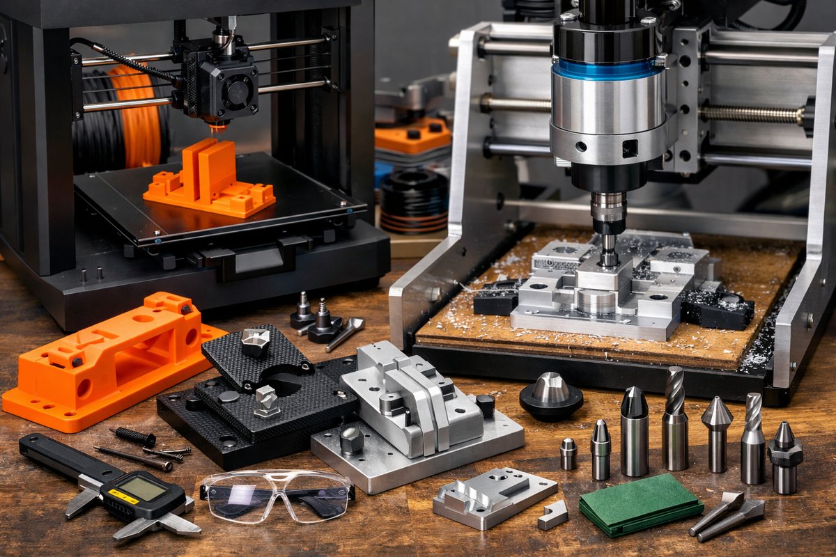
Discover how desktop FDM 3D printing can be paired with a compact CNC router to create high-precision jigs and fixtures. This step-by-step guide covers material selection, hardware setup, slicing parameters, and post-processing with end mills and router bits to unlock hybrid subtractive-additive workflows.
Additive manufacturing opens a world of possibilities for rapid prototyping, custom tooling, and small-batch production. Rather than carving away material, Fused Deposition Modeling (FDM) builds parts layer by layer from molten thermoplastic. Yet the marriage of 3D printing with CNC milling elevates accuracy, surface finish, and repeatability. In this guide, you’ll learn how to harness affordable hardware-a desktop FDM printer and a compact CNC router-to produce durable jigs, templates, and tooling aids with sub-millimeter precision.
Every successful hybrid workflow begins with a clear understanding of materials and hardware. PLA remains a go-to filament for its ease of use, dimensional stability, and minimal warping. Pair it with a hardened steel nozzle to handle abrasive colorants or composite blends. A silicone-textured build surface helps parts adhere while still releasing cleanly. Meanwhile, a desktop CNC router outfitted with a spoiler board, T-track clamps, and an integrated dust shoe offers the rigidity and dust management you need for precision milling. Treat both machines as complementary tools: the printer delivers near-net shapes, and the router refines the geometry to exact tolerances.
Start by modeling your jig or fixture in CAD software, paying close attention to functional features like locating pins, recesses, and mounting holes. Add a small offset-typically 0.2-0.3 mm-to surfaces that will receive a finish pass from the router. Export as an STL and import into slicing software. Set layer height to 0.2 mm for speed, or 0.1 mm if surface quality is critical. Infill at 20-30 percent balances strength with material usage. Enable a single solid top layer if you plan to remove material from that face. Disable supports under flat areas that will be machined later, reserving them only for overhangs that can’t be trimmed.
On the FDM printer, install your hardened steel nozzle and level the bed precisely using a paper or feeler-gauge method. Calibrate the extruder steps so that the filament diameter and flow rate produce accurate dimensions-print a 20 mm calibration cube and measure all axes. Adjust bed and nozzle temperatures based on filament manufacturer recommendations, typically 200-210 °C for PLA with a heated bed at 60 °C. Slow the initial layer print speed to 20 mm/s to ensure good adhesion, then accelerate to 40-50 mm/s for subsequent layers.
Once the part is printed, remove it gently from the build surface. Take time to trim any stringing or small burrs with flush cutters. Use a deburring tool on chamfered edges that will mate with other parts. If you encounter visible layer lines on faces destined for finishing, slightly oversize those surfaces in your CAD model or increase infill density to stiffen the part during milling.
Dimensional accuracy in FDM is rarely perfect out of the box, which is where CNC finishing shines. A compact 3-axis router can hold repeatable tolerances down to 0.1 mm when properly set up. Secure a flat spoil board on the machine’s bed, and use T-track fixtures or double-sided adhesive tape to hold the printed part. Add auxiliary supports or a custom jig to prevent vibration for taller prints. Probe the part’s top surface with a touch sensor or a simple paper-thickness method to establish the Z zero plane.
Choosing the right cutting tool is key. For roughing, a 1/8-inch straight-flute carbide end mill will remove material quickly with minimal heat buildup. For finishing contours and smooth surfaces, a 1/4-inch ball-nose end mill runs at higher spindle speeds and leaves a more polished texture. Set a shallow depth of cut-0.5-1 mm per pass-and moderate feed rates of 200-300 mm/min for PLA. Adjust spindle speed to 12,000-15,000 RPM to minimize heat and prevent plastic from melting around the cutter.
With your tool selected, import the part’s STL or the original CAD file into CAM software. Define a facing operation to flatten the top layer, then use 3D contour or pencil-mill strategies to follow curved features. Verify your toolpaths in simulation mode to avoid collisions. Generate G-code and load it onto the CNC router’s controller. Run the program with a dust-collection system engaged to capture plastic chips and keep the workspace clean.
After milling, inspect the finished surfaces with a caliper or a dial indicator. Replace or tighten any fixtures, then repeat passes if necessary. Small burrs along cut edges can be removed with a micro-file or fine-grit sandpaper. For a smoother finish, dry-sand the part progressively from 200 to 600 grit. If you’re working with ABS instead of PLA, a gentle acetone vapor bath will fuse layer lines and yield a glossy exterior before milling.
Beyond purely functional edges, this hybrid method unlocks decorative possibilities. Carve lettering, inlays, or relief patterns directly onto printed panels. Use contrast filaments or dyes to fill engraved features. Assemble multiple machined-printed components with press-fits, threaded inserts, or adhesive bonding to build complex jigs for drilling guides, PCB holders, or router templates.
In real-world use, these parts stand up to shop conditions. Nylon or PETG filaments boost impact resistance, while reinforced blends handle higher temperatures. When machining high-wear surfaces like alignment rails, consider embedding brass or stainless steel inserts in the print phase, then trim them flush with the router. Incorporate cable channels, mounting holes, and ergonomic grips all in one workflow.
The synergy of additive and subtractive manufacturing fosters a mindset of experimentation and continuous refinement. Start with simple jigs and fixtures to build confidence, then tackle more ambitious multi-axis parts, spring-loaded assemblies, or interlocking mechanisms. Document your machine settings, feed and speed parameters, and CAM strategies. Share your findings with online communities to accelerate collective learning.
Whether you’re an electronics hobbyist, a woodworking enthusiast, or a small-batch fabricator, this approach will expand your toolkit. You’ll gain the speed of FDM printing for rapid iteration, along with the precision of CNC routing for final adjustments. Embrace the discipline of both processes-layer by layer and pass by pass-to reveal parts that are as functional as they are refined. The hybrid pathway invites curiosity, rewards patience, and brings the craft of subtraction to the world of addition. Take that first printed part, fire up the router, and discover how subtraction can complete your additive vision.












