Location
Mount Vernon, WA 98274

Location
Mount Vernon, WA 98274
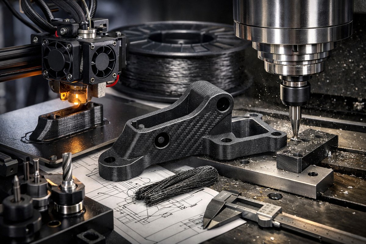
Discover how to harness the strength of carbon-fiber reinforced Fused Deposition Modeling (FDM) and refine your prints with CNC milling. This detailed guide walks you through essential components, printer setup, slicing parameters, post-processing, and router integration for hybrid manufacturing that produces durable, precision parts.
Additive manufacturing has transformed prototyping and small-batch production by building parts layer by layer. Yet pure FDM prints can lack the stiffness and surface fidelity that metal or machined plastics deliver. By integrating composite Fused Deposition Modeling techniques-using carbon-fiber or glass-fiber reinforced filament-with purpose-built machining tools, you can achieve parts that combine lightweight strength with crisp, finished surfaces. This guide reviews the steps and components you need to master composite FDM printing and follow up with CNC router finishing in your own workshop.
Composite FDM: Strength Meets Versatility
A standard PLA or ABS print can flex under stress, making it unsuitable for jigs, fixtures, or load-bearing prototypes. Composite FDM uses a base polymer blended with short or continuous fibers-often carbon or glass-to boost rigidity, heat resistance, and dimensional stability. The fibers distribute load across the matrix, reducing warping and improving tensile performance. When you add CNC finishing after printing, you unlock true precision: flat faces for mounting, tight hole tolerances, and glossy edges that require no additional coatings.
Essential Components for Composite Printing
To print composite filaments reliably, you must upgrade beyond stock FDM parts. A hardened steel nozzle resists abrasion from the embedded fibers, maintaining orifice geometry over hundreds of hours. An all-metal hotend keeps temperatures stable above 230 °C, preventing clogs and polymer degradation. A heated bed with precise temperature control (up to 100 °C for Nylon blends) ensures adhesion while minimizing curl. Finally, a well-calibrated extrusion system with a high-torque stepper motor delivers consistent filament flow and accurate retraction.
Preparing Your FDM Printer
Start by installing the hardened steel nozzle and verifying proper nozzle height above the bed. Level the bed manually or with an automated probe, then adjust first-layer flow to 100-105 percent to compensate for fiber content. Upgrade your PTFE-free Bowden or direct-drive hotend to handle abrasive materials. If your machine has a heated chamber, set it between 40 °C and 60 °C to reduce thermal shock. Check all Bowden tube fittings and tighten the hotend coupling collar to prevent slippage under higher extrusion forces.
Slicing and Print Settings
Load your carbon-fiber filament spool and configure slicing parameters. Recommended starting settings:
– Nozzle temperature: 230 °C-250 °C (adjust in 5 °C increments for optimal layer adhesion)
– Bed temperature: 60 °C-80 °C (Nylon blends may require up to 100 °C)
– Layer height: 0.15 mm-0.25 mm (lower heights yield finer surface finish but longer prints)
– Print speed: 30-50 mm/s (slower speeds reduce backpressure and improve fiber distribution)
– Infill density: 40-60 percent (higher densities maximize stiffness)
– Perimeters: at least 3 walls to fully enclose infill and distribute loads across outer fibers
– Cooling fan: off or at 10 percent, depending on polymer matrix recommendations
Always run a small calibration cube to verify dimensional accuracy and note any Z-over-extrusion or under-extrusion. Adjust flow multiplier by ±2 percent until walls measure within 0.05 mm of nominal.
Managing the Print Process
Composite filaments can be prone to jams if the hotend over-heats or if retraction is excessive. Disable too-long retractions and lower retraction distance by 0.5-1 mm to prevent melted material from depositing in the heat break. Monitor the first few layers for fiber flaring-tiny bits of fiber that escape around the nozzle. If you see these, lower the nozzle temperature by 5 °C or slow the print speed. After each print, clean the nozzle with a cold-pull using a standard PLA or Nylon cleaning filament to remove any residual debris.
Post-Processing Before Machining
Once the print is complete, let it cool fully on the bed to avoid warping. Remove the part gently and inspect layer adhesion at corners. For parts with minor surface defects, you can use a fine grit sandpaper (400-600 grit) to smooth over layer lines. For ABS-based composites, a brief vapor-acetone treatment in a sealed chamber can blend layers into a glossy surface, but test on scrap material first to avoid overexposure. Mark critical edges and mounting faces with a pencil: these will guide your CNC toolpaths and fixture setup.
Setting Up CNC Finishing
To achieve machined tolerances and flat surfaces, a small CNC router or desktop milling machine is ideal. Secure the printed part to a vacuum hold-down table or a soft wood sacrificial spoil board using double-sided tape and push-pins around the perimeter. Zero your machine axes on an edge or a dedicated datum pin, then load a 2-flute tungsten carbide end mill with a 2 mm or 3 mm diameter. This bit size balances rigidity with minimal deflection when cutting fiber-reinforced polymers.
Toolpath Strategy
Use a simple facing toolpath to skim the top surface, then switch to a contour pass for mounting holes and critical edges. Set spindle speed to around 12,000-16,000 RPM and feed rate to 500-800 mm/min. Because carbon fibers are abrasive, keep the chip load conservative: around 0.03 mm per tooth. If you hear a high-pitched squeal, reduce spindle RPM or increase feed slightly. For precise holes, use a drill bit one size under the final diameter, then finish-bore with a small boring head or reamer to achieve ±0.05 mm accuracy.
Safety and Best Practices
Always wear a respirator rated for fine dust when machining fiber-reinforced parts. The shredded carbon and polymer particles can be harmful if inhaled. Use a dust collection system or enclosure to capture airborne debris. Inspect end mills after each job-abrasive fibers will dull carbide quickly, so swap bits when you see surface chatter or burned polymer edges.
Design Tips for Hybrid Manufacturing
When modeling parts, add small chamfers or fillets to edges you plan to machine; this reduces tool wear and prevents edge break-out. Include mounting tabs or datum surfaces that your CNC setup can reference. If you need continuous fiber reinforcement, consider slicing your model into two halves along the fiber direction, printing with continuous fiber deposition, then gluing and machining the seam for a smooth transition.
Bringing It All Together
By combining carbon-fiber reinforced FDM printing with CNC finishing, you get the best of both worlds: parts that are lightweight and strong straight off the printer, then refined to precise geometries and smooth surfaces through subtractive machining. This hybrid workflow opens up applications in functional prototypes, jigs and fixtures, brackets, and even small mechanical assemblies. With the right components-hardened steel nozzles, high-temperature hotends, reinforced filaments, and capable CNC tooling-you’ll unlock a new level of performance in your additive manufacturing projects.
Ready to experiment? Gather your upgraded FDM components, load that spool of composite filament, and fire up the CNC router. The marriage of additive and subtractive processes awaits, and your workshop is the stage where raw innovation takes shape through cycles of build, test, and refine.












