Location
Mount Vernon, WA 98274

Location
Mount Vernon, WA 98274
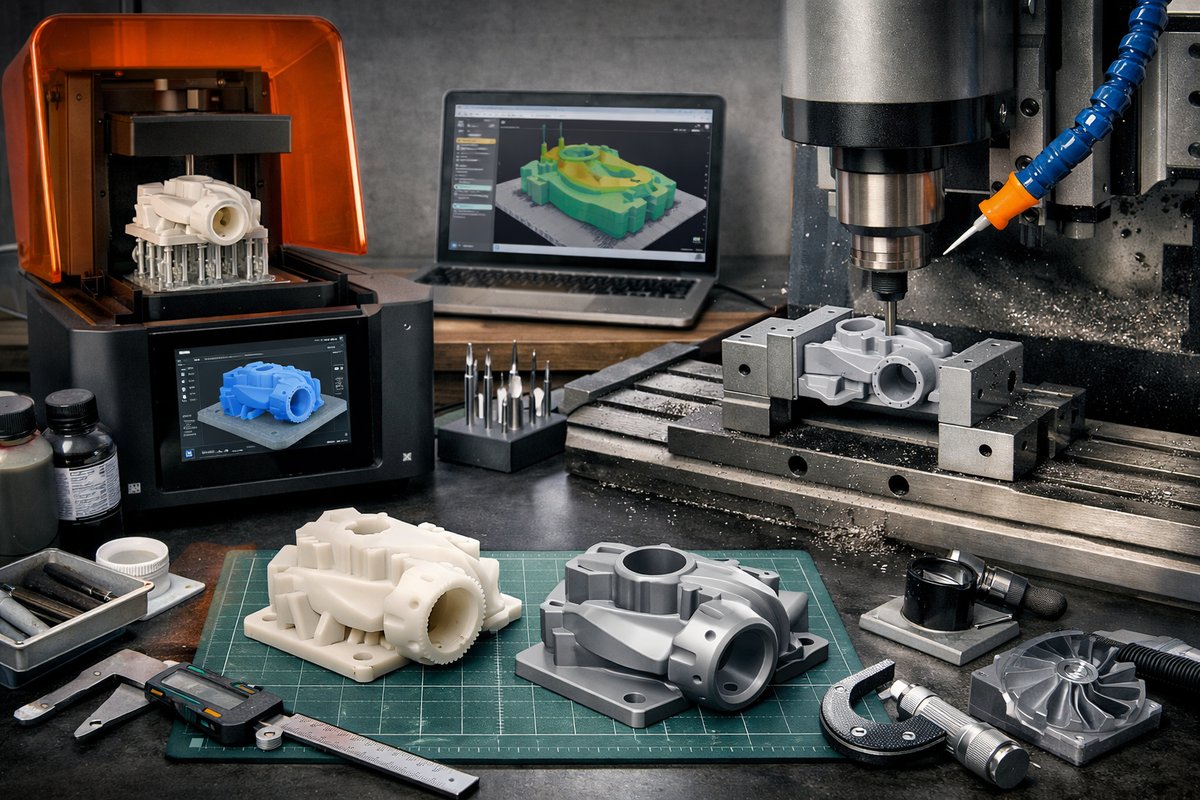
Discover a step-by-step approach to combining resin-based SLA printing with desktop CNC milling to achieve ultra-smooth surfaces, tight tolerances, and professional-grade prototypes. This guide covers essential hardware, software settings, post-processing techniques, and precision finishing strategies aimed at curious makers and small workshops.
Additive manufacturing has evolved beyond standalone 3D printing. By combining the high resolution of resin stereolithography with the precision of CNC milling, you can unlock a new tier of surface quality and dimensional accuracy. This hybrid workflow bridges the gap between the intricate detail that only SLA can deliver and the crisp edges and tolerances achievable with subtractive methods.
At its core, stereolithography uses a laser or LCD projector to cure liquid photopolymer resin layer by layer. The result is a part with smooth walls, fine features, and minimal layer lines. Yet even the smoothest SLA print may require secondary operations to reach tolerances under 0.2 mm or to refine sharp corners and mating surfaces. Desktop CNC milling machines step in to refine those areas, adding precision where the resin process leaves subtle variances.
Before diving in, prepare your workspace. A well-ventilated area and a sturdy workbench are essential. Youll need a resin SLA 3D printer, a UV curing station, and a desktop CNC mill. Safety gear includes nitrile gloves, a respirator rated for organic vapors, and protective eyewear. Precision tools like digital calipers and a small adjustable vise will help you measure and hold prints during milling.
Software drives the process. Choose a slicing application that supports your SLA hardware and lets you fine-tune layer thickness down to 25 or 50 microns. Software such as ChiTuBox, PrusaSlicer with SLA profiles, or proprietary printer platforms will let you set fill density, expose times, and build plate temperature if applicable. For the CNC stage, CAM programs like FreeCAD Path Workbench or commercial CAM suites generate toolpaths for roughing and finishing passes.
When slicing your model for SLA, orientation matters. Tilt the part 10 to 30° to minimize overhangs and reduce support contact on critical faces. Denser supports around thin pillars and curved flanges ensure stability. Use a layer height of 50 microns for general prototypes, dropping to 25 microns when capturing hair-fine details or lettering. Higher layer resolution translates to longer print times, so balance detail needs with project deadlines.
Once printing is finished, carefully remove the build plate and separate the part using a flexible scraper. Submerge the model in a bath of 90 percent isopropyl alcohol for 3 to 5 minutes, gently agitating to wash out uncured resin. Air dry in a dust-free area before moving to the curing station. A 2 to 5 minute UV cycle per side fully hardens the polymer, boosting mechanical strength and stabilizing dimensions ahead of milling.
Design for hybrid finishing by adding oversize allowances where you plan cutting passes. For example, if a hole must fit a 6 mm pin, model it at 6.5 mm in the SLA file. The extra material ensures the CNC bit removes resin in a clean, consistent cut without chattering. Similarly, flat faces destined for end-mill finishing can be left unpolished in the initial print to help workholding without slippage.
Set up your CNC mill by mounting the cured SLA part in a low-pressure vise or on a magnetic table if you use a ferrous build plate. Install a ball nose end mill for contour work or a small flat end mill for planar surfaces. Zero the X, Y, and Z axes at a reference corner or on a calibration block. Confirm tool length with an electronic probe or touch plate for consistent depth control.
Divide your CAM toolpath into three stages. Begin with a roughing pass using a 2 mm flat end mill at moderate stepover to remove bulk material. Keep spindle speeds around 10,000 to 12,000 RPM and feed rates around 500 mm per minute to prevent resin melting. Next, a semi-finish pass with a 1.0 mm ball nose bit refines curvature and removes most scallops, using lighter stepover and slower feed rates. Finally, a finishing pass at 0.1 mm stepover with the same ball nose cutter polishes surfaces to a mirror-like quality.
Throughout milling, monitor for chatter or tool deflection. If the surface shows ridges or strain marks, reduce feed rate or increase spindle speed slightly. Air blast the cutting zone with a handheld air gun to clear chips and maintain a consistent cut. Avoid cutting fluids that could attack photopolymer resins; clean with a dry brush or compressed air instead.
After finishing, inspect key dimensions using digital calipers or a micrometer. Check hole diameters, slot widths, and flatness across mating surfaces. If dimensions exceed tolerance, adjust your CAM offsets or change the bit diameter in future runs. Repeat small test cuts on a scrap SLA print to dial in accuracy before committing to final parts.
This hybrid workflow excels for injection mold prototypes, jigs, tooling fixtures, and detailed demonstration models. By starting with SLA, you capture textures, undercuts, and fine textures that would be arduous in pure milling. The CNC stage then polishes edges, flattens critical faces, and cuts precise holes-melding the best of both subtractive and additive worlds.
In practice, experiment with different bit geometries. A tapered ball end mill can reach tight fillets, while a straight flute bit may excel on simple planar surfaces. Test resin brands for hardness and surface finish-some UV-resistant formulations yield sharper edges after curing and tolerate milling stresses better.
By mastering each step-from slicing orientation to post-processing cure to toolpath generation-youll consistently produce prototypes with glossy surfaces, sharp corners, and reliable fits. This synergy transforms desktop machines into a micro-factory capable of professional-grade results in hours instead of days.
Push your creativity further by incorporating multi-material assemblies. SLA printed components can snap together or thread into CNC-milled housings, enabling complex mechanical prototypes. As workflow fluency grows, so does your ability to innovate without waiting on external job shops.
The path to high-precision hybrid manufacturing demands patience and calibration, but the payoff is professional surfaces, consistent tolerances, and the pride of craftsmanship. Gather your resin printer, curing station, desktop CNC mill, and precision tools, then embrace this subtractive-meets-additive dance-your prototypes will never look back.












