Location
Mount Vernon, WA 98274

Location
Mount Vernon, WA 98274
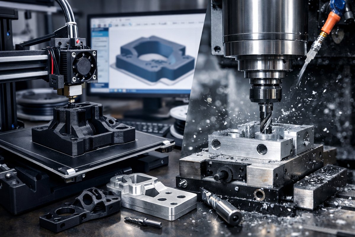
Discover how to combine Fused Deposition Modeling (FDM) 3D printing with CNC milling for precision parts. This guide walks through equipment setup, material selection, digital preparation, and finishing techniques that bridge additive flexibility with subtractive accuracy.
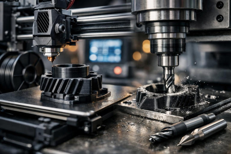
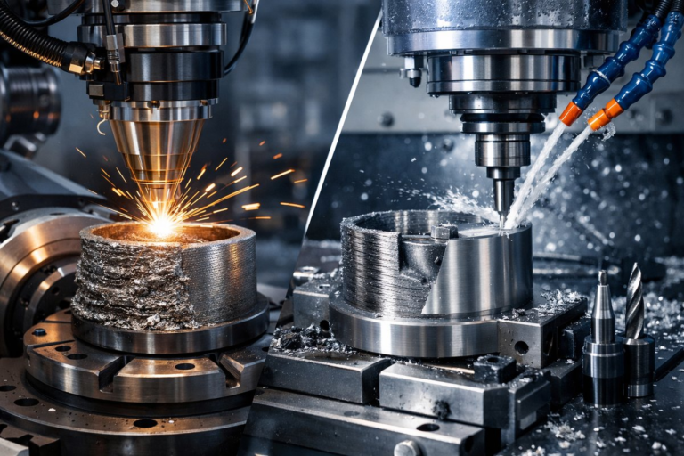
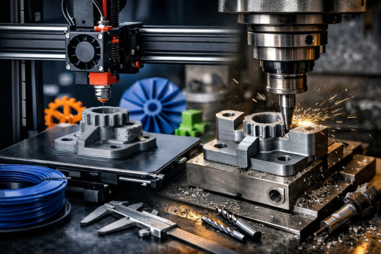
Expanding a traditional machine shop toolkit with additive manufacturing opens up new pathways for rapid prototyping and custom geometries. By integrating Fused Deposition Modeling (FDM) 3D printing with a CNC milling router, you gain the ability to produce complex shapes in plastic before refining critical surfaces to tight tolerances through subtractive passes. This hybrid workflow minimizes material waste and compresses lead times, making it ideal for small-batch runs and one-off parts.
FDM remains one of the most accessible and cost-effective forms of 3D printing. It uses a heated nozzle to deposit thermoplastic filament layer by layer, building up the part with predictable mechanical properties. When combined with a CNC mill, you can print a near-net-shape blank in PLA, PETG, or ABS and then machine functional features-flat surfaces, holes, or threaded pockets-to sub-0.1 mm accuracy.
Before you dive in, map out your hybrid workflow. 3D print the general form first, taking advantage of internal lattices, hollow cavities, or organic contours that would be difficult or impossible to mill from a solid block. Then switch to the CNC side of the workshop for precision cuts on mounting faces, sealing flanges, or high-tolerance interfaces where FDM alone falls short.
At minimum you’ll need a desktop FDM printer with a build volume large enough for your part, a CNC milling router with a rigid bed, a set of end mills (both roughing and finishing), a workholding kit, and common shop accessories like a digital caliper. For higher throughput, consider an enclosure for the printer to reduce warping, and a quick-change collet system on the CNC for faster bit swaps.
The digital model must accommodate both processes. In your CAD program, create the full 3D geometry, then split it into two separate files: one for the printed blank and one for the machined features. Include registration slots, dowel pins, or fiducial marks in the print design to help align the part on the CNC bed. These alignment points ensure that the subtractive operations map exactly onto the printed geometry.
Material selection is critical. PLA is user-friendly, dimensionally stable, and easy to print at moderate temperatures, making it a good candidate for non-load-bearing prototypes. PETG offers better impact resistance and thermal stability if you need a more durable blank. If you plan to mill into soft metal or composite stock instead of plastic, adjust your workholding and cutting parameters accordingly.
Use a slicing profile tailored for near-solid prints: layer heights of 0.2 mm or finer, infill densities over 50 percent, and multiple wall shells to create a dense outer envelope. This reduces internal voids that might affect the milling operation. Slow down travel speeds and disable ironing or coasting features to ensure a smooth, even surface.
Once printing is complete, carefully remove support structures and give the blank a light sanding to eliminate any pronounced layer lines. Clean the part with isopropyl alcohol or a gentle detergent to remove oils and debris. Proper cleaning helps the machine’s probe or touch-off routine detect the actual surface rather than a residue build-up.
On the CNC side, secure the blank with a modular vise or precision clamps. If you printed registration holes, insert dowel pins and clamp around them. For flat faces, use a spoil board with double-sided tape and vacuum if available. Make sure the part can withstand upcoming spindle forces without shifting or lifting.
Align the workpiece by probing or manually jogging the router head to each fiducial. Zero your X, Y, and Z axes using either a touch probe or a paper-feel gauge. Accurate alignment is crucial-errors here will propagate through every milled feature, negating the benefits of your additive preform.
Choose an end mill appropriate for the material. A 4-flute carbide finishing bit around 2 mm in diameter offers a good balance of rigidity and surface finish for PLA or PETG. For bulk removal, use a larger two-flute roughing end mill. High-speed steel bits can also work but may dull faster when cutting abrasive composites.
Program the toolpaths so that the roughing pass removes most of the bulk plastic quickly, using high feed rates and larger stepover. Then switch to the finishing bit for a lighter radial depth of cut-0.1 mm or less-at spindle speeds exceeding 15,000 RPM. The result is smooth faces ready for functional mating with metal hardware or seals.
After machining, inspect critical dimensions with digital calipers or a height gauge. Check flatness across faces using a precision straightedge or dial indicator mount. If you see slight tool marks, a very light polish with fine-grit sandpaper or a polishing compound can bring out a glossy finish. Avoid overheating the plastic during polishing or you may introduce warping.
This hybrid approach delivers parts that combine the creative freedom of additive manufacturing with the precision surfaces of subtractive machining. You can iterate on concepts quickly by revising the printed blank, without re-fixturing expensive metal stock. And because the print handles most of the geometric complexity, cycle times on the CNC tend to be shorter than if you machined a block from scratch.
To get the best results, maintain your machines rigorously. Keep the printer’s bed level and nozzle clean. Lubricate the CNC rails and check belt tensions. Calibrate the Z-axis probe regularly. A small misalignment or loose screw can amplify errors when you’re working to tenths of a millimeter.
Embrace experimentation. Try different infill patterns to see how they machine. Test offset surfaces printed at slight oversize to dial in the perfect fit after machining. And document each iteration-settings, bits, speeds-so you build up a library of successful recipes for future projects.
Whether you’re crafting functional prototypes, custom tooling, or small series parts, hybrid additive and subtractive manufacturing unlocks capabilities that neither method can achieve alone. With the right combination of filament, end mills, and workflows, you’ll transform your workshop into a powerhouse of precision and creativity.