Location
Mount Vernon, WA 98274

Location
Mount Vernon, WA 98274
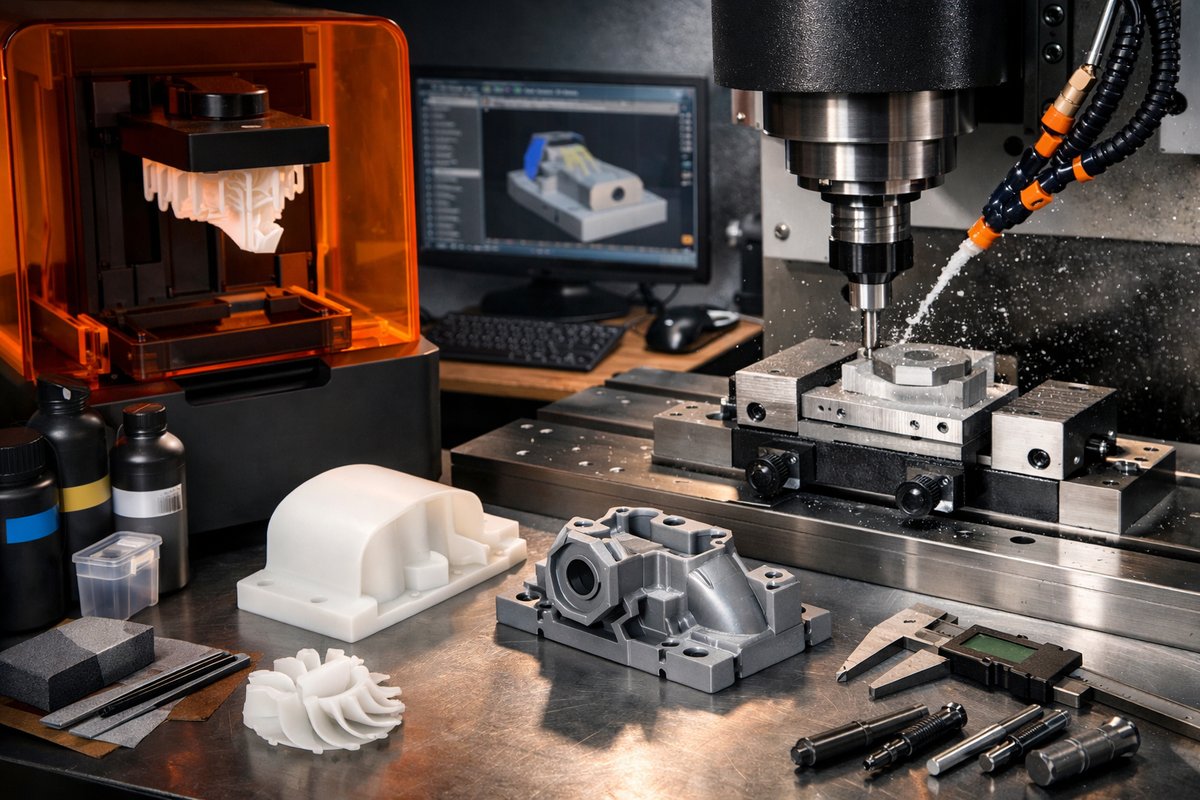
Discover how to combine stereolithography 3D printing with CNC milling to achieve exceptional surface quality and dimensional accuracy. This step-by-step guide reviews resin selection, printer setup, post-processing, fixturing techniques, tooling choices, and machining strategies to help you deliver parts ready for demanding engineering applications.
Additive and subtractive processes each have their strengths: one builds complex forms layer by layer, the other refines surfaces with razor-sharp tools. By bringing stereolithography (SLA) resin printing together with CNC milling, you tap into the best of both worlds. You can produce intricate geometries in minutes and then uncover smooth faces, crisp edges, and tight tolerances through light machining passes. Whether you’re a hobbyist leveling up or a small-batch shop pushing precision limits, this hybrid workflow can save time, reduce manual sanding, and deliver parts that gleam like they were cast and polished.
The secret lies in treating your resin print not as a finished object but as a near-net shape ready for subtraction. You design with milling allowances in mind-adding a few tenths of a millimeter of extra material wherever you plan to touch up critical surfaces. After the print comes off the build plate, you wash, cure, and mount it securely in your CNC router. Carefully chosen end mills and calibrated feeds let you skim away resin flashes and layer lines, revealing geometry that would be impossible in either process alone.
Start with the digital model. In your CAD software, identify datums-reference faces you’ll use to align the part in the router. On those faces, add an offset of 0.2-0.5 mm. This extra resin acts as a sacrificial zone for your finish passes. Export an STL with high mesh density to preserve detail, then import it to your SLA slicer. Choose a layer thickness around 50 µm for a balance of speed and surface uniformity. Orient the part so that the most critical surfaces face upward or sideways, avoiding overhangs on precision faces.
Next, set up your SLA printer. Clean the resin vat and inspect the FEP film for scratches. Fill with a low-viscosity photopolymer designed for mechanical strength rather than extreme flexibility. Level the build plate carefully-poor leveling leads to variable layer thickness and makes your finishing passes inconsistent. Dial in the exposure time per manufacturer guidelines, then print. Keep ambient temperature stable; fluctuations can cause shrinkage that shifts dimensions by up to a few hundred microns.
Once the print finishes, remove it from the plate using a flexible scraper at a shallow angle to avoid gouging. Immediately place it in an isopropyl alcohol wash. Agitate gently for two to three minutes, or use a dedicated ultrasonic cleaner if available. After washing, let the part dry completely-any residual alcohol can interfere with post-cure. Transfer the part to a UV curing station and expose it for the recommended cycle, usually 10-15 minutes per side. Rotate part orientation halfway through to promote even cross-linking.
With the part cured and cooled, inspect it for unmelted resin beads or support nubs. Snip away supports with flush cutters, then lightly sand blends on non-critical areas to reduce stress risers. Now it’s time to bring in the CNC router. You’ll need a reliable hold-down method: double-sided machinable tape works for small pieces, while a vacuum table or friction plate can secure larger castings. Align your datum faces to the router’s X-Y axis, then lock the stock zero position in your controller.
Choose your tooling carefully. A precision ball-nose end mill-2 mm diameter with two flutes-lets you skim curved areas and maintain contour fidelity. For flat faces, a 4 mm two-flute flat end mill performs rapid light cuts. Slot these bits into a high-speed collet holder rated for at least 20,000 RPM. Set spindle speed to 15,000-18,000 RPM and start with a 0.5 mm step-over for finishing. Since cured resin is softer than aluminum, you can push feed rates to 500-800 mm/min. Depth per pass should stay under 0.2 mm to avoid chatter and melt zones.
Run a trial program on a scrap block of cured resin to verify toolpaths and feeds. Check for signs of melting, which show up as glossy edges or stringy chips. If you see these, increase feed rate to shear faster and reduce spindle speed slightly. Once the trial cut yields a consistent matte chip and clean edge, transfer the G-code to your main part. Execute a safe approach: rapid moves two to three millimeters above the surface, then plunge at 200 mm/min.
After finishing passes complete, remove the part and blow off chips with compressed air. Inspect the critical dimensions using a digital caliper or micrometer. You should find tolerances within ±0.05 mm on key faces-far tighter than what you can typically achieve with SLA alone. If any features still show layer lines or roughness, run a localized 0.1 mm finishing pass with a ball-nose end mill at 12,000 RPM and 300 mm/min.
Hybrid manufacturing shines when you need complex internal channels or thin walls that resist bending, combined with mirror-smooth mounting faces or sealed surfaces. It’s especially useful for tooling inserts, fluidic manifolds, and architectural models with sharp corners. The workflow reduces hand sanding by 80%, cuts cycle time by half, and elevates part aesthetics for presentations or functional tests.
To refine your process over time, keep these tips in mind:
– Monitor resin temperature: cold vats can cause over-curing and shrinkage. Keep resin between 20-25 °C.
– Replace FEP film every 100 builds to maintain layer consistency.
– Clean your end mills after each session: resin buildup dulls the edge and spoils surface finishes.
– Use a dust shoe on your router to collect resin dust and maintain a clean workspace.
– Record feed and spindle settings in a shared log so teammates can replicate perfect finishes.
Ultimately, marrying SLA printing with CNC milling is a journey of calibration and iterative improvement. Start small-print simple cubes with extra offsets, machine one face flat, and measure the result. As you dial in parameters, scale up to more intricate shapes. Soon you’ll be balancing additive freedom with subtractive precision, crafting parts that look and function as if they were injection molded or machined from solid billet. The quiet discipline of subtraction has never felt so progressive, and the art of addition gains new purpose when you learn to reveal the best in both methods.












