Location
Mount Vernon, WA 98274

Location
Mount Vernon, WA 98274
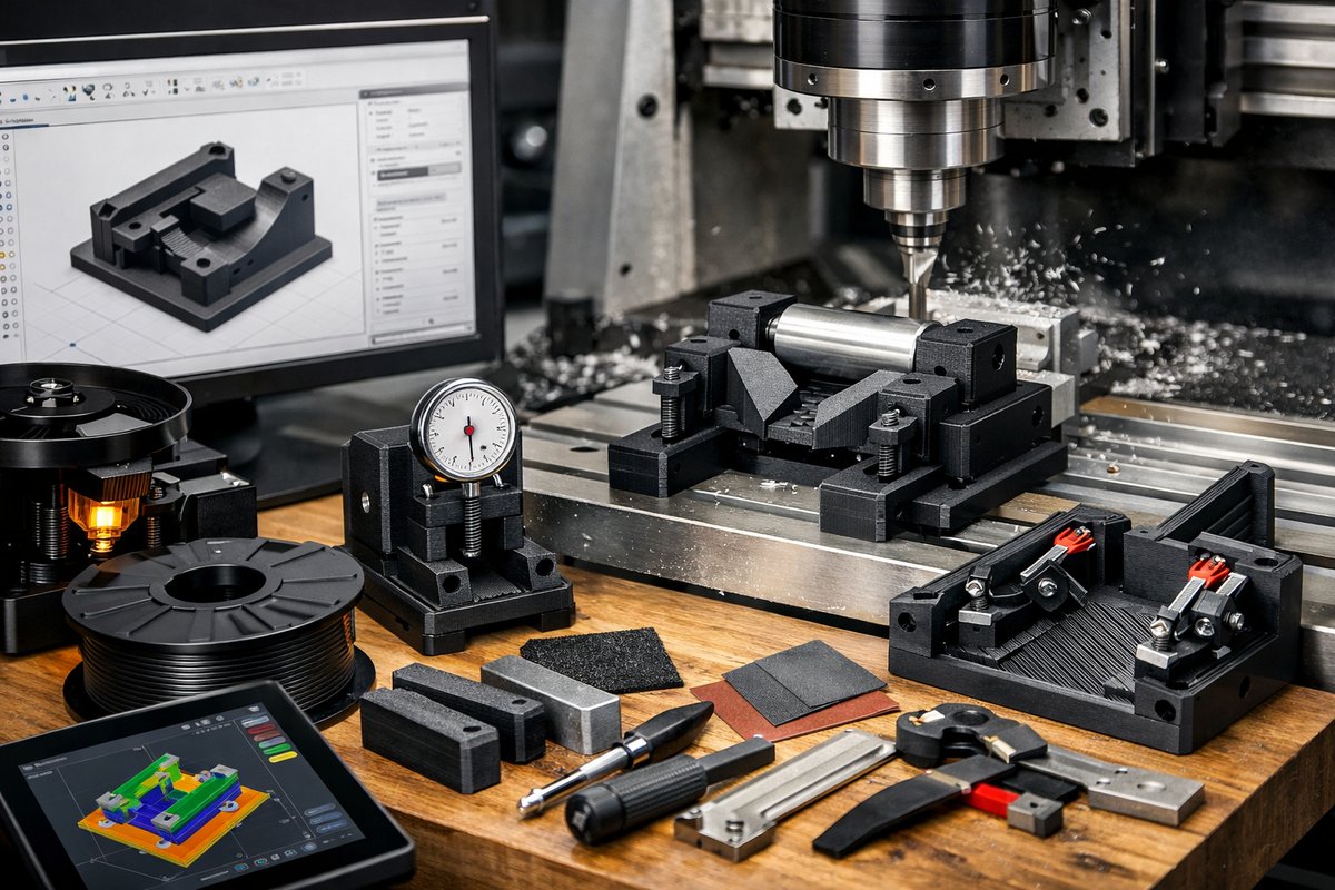
Discover how fused deposition modeling can empower your CNC workflow by producing custom jigs and fixtures. This guide walks through design in CAD, slicing strategies, material choices, and post-processing tips to achieve rigid, accurate add-on components that work seamlessly with routers, end mills, and CNC machines.
In a workshop where tradition meets innovation, a custom-printed jig can make all the difference. Additive manufacturing-specifically fused deposition modeling (FDM)-unlocks rapid iteration of fixtures, guides, and holders that slide into your CNC setup with minimal fuss. Instead of carving metal by hand or waiting on an external machine shop, you can design, print, and test a router bit guide or an end mill holder in a single afternoon. This article dives into the craft of FDM for subtractive workflows, reviewing key techniques and components so you can confidently build your first precision fixture.
Choosing the Right FDM Printer and Nozzle
For workshop-grade jigs you need a printer that holds tight tolerances. Look for an FDM machine with a rigid metal frame, heated bed, and stable Z-axis drive. CoreXY or belt-driven Cartesian setups balance speed and accuracy. A nozzle diameter of 0.4 mm is a versatile starting point-smaller nozzles (0.2 mm) yield finer detail but extend print times, while larger nozzles (0.6 mm) produce faster but coarser results. Consider a hardened steel nozzle if you plan to print abrasive filaments like carbon-fiber-reinforced PLA or PETG.
Material Matters: PLA, PETG, and Beyond
PLA prints easily but can soften under sustained heat. PETG offers a sweet spot: good layer adhesion, moderate flexibility, and higher temperature resistance-ideal for a jig that may endure the friction of a router bit. If you need extra rigidity, nylon or polycarbonate blends provide strength at the cost of more demanding print conditions (enclosed chamber, dry filament storage, stronger bed adhesion). Each choice reflects a sustainability trade-off: PLA is biodegradable, PETG is recyclable, and engineering plastics often contain additives. Prioritize materials you can reuse or recycle when your jig design evolves.
Designing Your Jig in CAD
Begin with a clear purpose. Do you need a linear guide for a router bit, a height gauge for an end mill, or a modular fixture for quick part swaps? In your CAD software, parameterize critical dimensions-hole diameter, guide height, clamp pressure-so you can tweak on the fly. Sketch the outline of your jig plate to match your CNC’s T-slot or grid pattern, then extrude connection points that mate with standard hold-down clamps. Incorporate fillets and chamfers to reduce stress concentrations around screw holes. Keep walls at least 3-4 mm thick to prevent cracking under load.
Slicing Settings for Accuracy and Strength
Import your CAD export (STL or 3MF) into a slicer. Set layer height between 0.12 and 0.20 mm for a balance of smooth walls and speed. For strength, use a 3-4 perimeter outline and a 30-50% infill-gyroid or grid patterns distribute force evenly. Disable or minimize support structures by designing overhang angles under 60 degrees. Activate ironing or a top-layer smoothing pass to create a flat surface where the router bit will bear down. If your slicer offers linear advance or pressure advance, tune it to reduce filament oozing and improve corner accuracy.
Printing and Post-Processing
Start with a clean, leveled bed and a light coat of adhesive (glue stick or specialized bed spray). Print at suggested filament temperatures-typically 230-250 °C for PETG, 200-220 °C for PLA. Monitor the first few layers to confirm good adhesion. Once printing completes, carefully remove the part to avoid warping. Trim any stray strings or support remnants with flush cutters. For critical mating surfaces, gently sand with 200-400 grit sandpaper on a flat block. If you need a perfectly square face, secure the jig in a vise and briefly pass a fine end mill or router bit over the face at low speed-this hybrid step marries additive convenience with subtractive precision.
Integrating the Jig into Your CNC Workflow
Mount the printed jig on your CNC bed using T-slot clamps or M-slot nuts. Zero your axes on the jig’s reference points, then run a shallow test cut with the intended end mill or router bit. Watch for any flex or movement-if you notice slight shifts, tighten clamping, or add a backing plate beneath the jig. Once secured, you can machine patterns into raw stock held by the jig or use it as a drill guide for repetitive hole patterns. The printed fixture becomes a dedicated tool, freeing your main setup for other tasks.
Iterate and Refine
No first print is perfect. Maybe the bit guide is too tight, or the clamp slots are misaligned. Update your CAD parameters, re-slice, and print again. Each cycle teaches you more about printer behavior, material quirks, and mechanical fit. Over time you’ll assemble a digital library of proven jigs-an ecosystem of fixtures you can modify for new projects in minutes. This iterative loop embodies both additive freedom and subtractive discipline: you add layers, then take away imperfections, forging precision out of trial and error.
Future-Proofing and Sustainability
Keep digital archives of each jig version so you can revisit or print replacement parts years later. Consider offering open-source licenses if you build a unique fixture that benefits the community. When a jig finally reaches end-of-life, grind it into filament-compatible granules or donate to a filament recycler. By blending additive innovation with subtractive respect, you maintain a low-waste workshop and a high-throughput production line.
A Call to Curious Makers
FDM 3D printing is more than a novelty-it’s a practical extension of any CNC shop. Whether you need a quick drill guide, a specialized clamp, or a dedicated router bit holder, the barrier to entry is low and the creative payoff is high. Embrace the patience of design, the precision of slicing, and the perseverance of trial prints. In each printed jig you uncover hidden potential-objects revealed not by cutting away, but by building up, layer by layer, until purpose emerges from plastic.
Ready to push the boundaries of your workshop? Grab your CAD file, fire up the slicer, and watch additive and subtractive manufacturing converge in a custom jig you built yourself.












