Location
Mount Vernon, WA 98274

Location
Mount Vernon, WA 98274
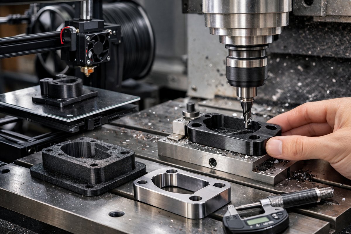
Combine the versatility of desktop FDM 3D printing with the razor-sharp accuracy of CNC machining. This step-by-step guide walks you through designing, printing, and then routing printed parts to achieve tight tolerances and glass-smooth finishes.
Additive manufacturing has made rapid prototyping accessible to hobbyists, engineers, and makers alike. Yet even the best FDM prints often fall short of the tolerances and surface quality demanded by functional jigs, fixtures, or end-use parts. That’s where subtractive techniques come in. By marrying the speed and design freedom of FDM plastic extrusion with the pinpoint precision of a CNC router and a fine ball nose end mill, you can bridge the gap between concept and mechanical repeatability.
Imagine designing a custom drill guide that perfectly aligns holes for a woodworking project, or a fluid manifold with channel depths accurate to a few thousandths of an inch. You start with a durable PLA or PETG print, then load it into your desktop CNC for a final pass to clean up features, tighten mounting holes, and polish critical surfaces. The result combines the best of both worlds: rapid iteration before machining and sub-millimeter precision afterward.
First, sketch out your part in CAD, paying attention to wall thickness, overhangs, and mounting points. Keep walls at least 3-4 millimeters thick when you know you’ll route them, so you have enough plastic for the cutter to engage. Plan your hole patterns or slots with tolerances of +0.2 millimeters for the FDM print, knowing you’ll dial in the final size with a CNC end mill. Label datum faces in your model so you can orient the part consistently in the router vise.
When exporting for 3D printing, slice at a 0.2 millimeter layer height and 30-40 percent infill for rigidity. Use a hardened steel nozzle-even with abrasive filaments like carbon-fiber-filled PLA-to avoid premature wear and maintain sharp extrusion. Make sure your heated bed is leveled and coated lightly with a glue stick to ensure solid first-layer adhesion. Disable excessive fan speeds on the lower layers to prevent warping, then ramp fans up to 100 percent after two or three layers for crisp details.
Once the print is complete, let it cool on the bed for 10-15 minutes before removal to avoid edge lifting. Trim supports and burrs with flush cutters, then lightly sand critical faces with 220-grit paper to remove visible layer lines. Clean the part with isopropyl alcohol to eliminate dust and oils before moving to your CNC setup.
Secure your printed workpiece in a desktop CNC router using an aluminum clamp kit or a spoilboard and double-sided tape for larger parts. Zero your tool on a flat reference face: touch off your X and Y axes against a sighting gauge or edge finder, then touch the cutter gently down on the work surface and zero Z. Use a soft probe if available to speed up the process and avoid dings.
Selecting the right cutter is crucial. A 1/8 inch carbide ball nose end mill with two flutes balances rigidity and finish. The small corner radius rides smoothly over curved geometries left by the 3D printer, leaving a glass-like finish on vertical and horizontal surfaces alike. For straight slot walls, consider a 1/8 inch square-end carbide bit. Always choose bits rated for plastics to avoid melt-through or chatter.
In your CAM software, create separate toolpaths for roughing and finishing. For the roughing pass, let the cutter remove infill ridges with a shallow stepover of 0.5 millimeters and an axial depth of cut of 0.5 millimeters. Program a finishing pass with a 0.1 millimeter stepover to leave just a whisper of material-enough for a smooth surface without overloading the bit. Don’t forget to include lead-in and lead-out moves to prevent tearing at the start and end of each pass.
When setting spindle speed, aim for 12,000 to 15,000 revolutions per minute and a feed rate of around 500 millimeters per minute for PLA. If you hear chirping or see plastic strands melting, increase feed slightly or reduce speed. For tougher filaments like PETG, lower spindle speed to 8,000 RPM and slow the feed by 10 percent. Always keep an eye on chip evacuation-packed chips can cause binding and surface gouging.
After machining, remove the part and blow off chips with compressed air or a soft brush. Inspect critical dimensions with an electronic caliper, checking holes, slots, and reference planes against your CAD tolerances. If surfaces still show faint ridges, a quick wipe with a polishing compound on a felt wheel will bring out a mirror finish.
Throughout the process, mind dust extraction and personal protection. A small shop-vac hooked to the router keeps plastic particles out of the air, preserving both tool life and respiratory health. Change or clean your end mill after every 300 minutes of cutting to maintain crisp edges.
Hybrid add-and-subtract workflows expand your capability beyond what stand-alone FDM or CNC machines offer. Rapid iteration on the printer lets you prototype geometry in hours, while the CNC brings final tolerances within thousandths. Whether you’re making jigs, housings, or functional prototypes, this approach slashes blending and polishing time while boosting repeatability.
The next time your printed part falls short on fit or finish, don’t reach for sandpaper alone. Think about a quick CNC pass to dial in your geometry, then polish. With a calibrated digital caliper in hand and the right carbide bits in your collet, you’ll turn rough plastic layers into precision tools in a fraction of the time. Grab your design files, fire up the slicer, and let a hybrid build become your new standard for accuracy and efficiency.
Ready to bridge the gap between speed and precision in your workshop? Gather your filament, clamp kit, router bits, and CNC machine. Dial in your design, print it out, and watch the magic happen when additive meets subtractive. Your next functional fixture or mechanical prototype is only two toolpaths away.












