Location
Mount Vernon, WA 98274

Location
Mount Vernon, WA 98274
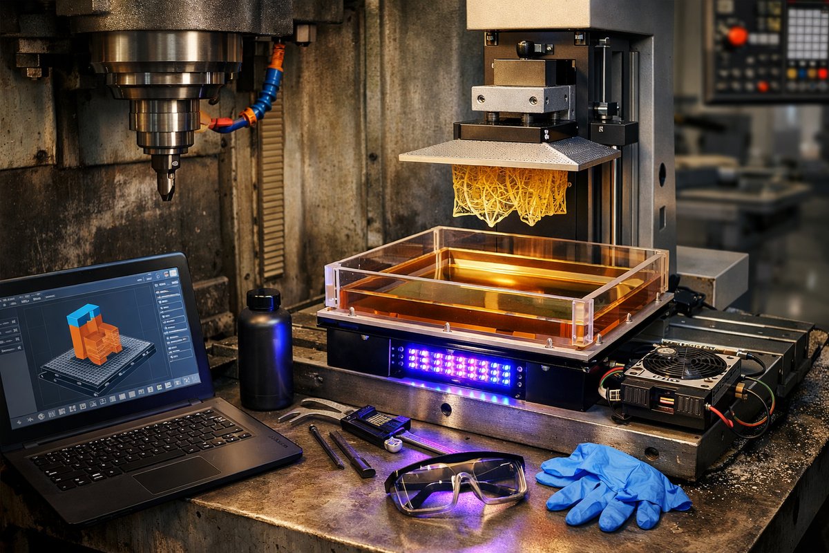
Discover a hybrid workflow that marries the pinpoint accuracy of CNC machining with the design freedom of stereolithography. This step-by-step guide shows how to retrofit a typical CNC mill for bottom-up resin printing, covering vat fabrication, UV LED installation, Z-axis calibration, slicing software, and safety practices.
Machinists know that taking away material can reveal shapes with razor-sharp precision. But what if you could add intricate features layer by layer using the same sturdy platform you trust for milling? By converting a standard CNC mill into a bottom-up SLA (stereolithography) printer, you gain both subtractive and additive power in one machine. This approach repurposes your machine’s rigid gantry, precision ball screws, and familiar CAM controls for resin-based 3D printing. The result: detailed, high-resolution parts ready for final machining or direct use.
Start by planning your build. List the core components you already have: a CNC mill with at least 300 mm of Z travel, a high-torque stepper motor on the Z-axis, and a control board that accepts G-code. Next, identify what’s missing: a leak-proof resin vat, a 405 nm UV LED curing source, a transparent build platform, and safety gear like UV-blocking goggles and nitrile gloves. Sketch the vat dimensions to ensure it fits on your mill table while leaving room for the collet, tool holder, or a quick-release fixture plate.
Fabricating the resin vat is the first major task. Use the CNC mill itself to cut an acrylic sheet into a flat bottom and side walls. Choose cast acrylic for its chemical resistance. Mill a shallow pocket in a 6 mm thick acrylic sheet for the transparent window, and carve the sides from a 10 mm sheet. Bond the pieces with solvent cement to create a rectangular tub. Apply a silicone gasket around the window’s perimeter to seal the joint. After assembly, pressurize lightly with water to check for leaks before adding resin.
With the vat secured to the table using T-slot clamps or a custom fixture plate, turn to the build platform. A thin aluminum plate, around 2 mm thick, works well. Drill and tap holes for a quick-release ring or magnetic clamp so you can remove prints easily. Sandblast the plate lightly to give first-layer adhesion without supports. Attach flexible build plates or a textured sticker if desired. Then mount the platform plate to the Z-axis ram or quill with standard tool-holder hardware-no need for extra adapters.
Installing the UV LED curing source requires careful positioning. Bottom-up SLA cures each layer through the vat’s acrylic base, so the LED array must sit directly beneath the transparent window. Choose a high-intensity 405 nm LED bar or panel rated for even light distribution. Build a mounting bracket from anodized aluminum; use vibration-damping rubber feet so the curing unit doesn’t affect your mill’s positioning accuracy. Wire the LEDs to a dimmable constant-current driver that you can switch on and off with a relay or solid-state switch triggered by G-code M commands.
Next comes Z-axis calibration. Resin layers in SLA are typically 25-100 microns thick. That demands reliable step resolution and minimal backlash. Check the ball screw preload and tighten anti-backlash nuts until you eliminate motion slack. Use your control software to set microstepping to at least 1/16 or higher, and verify the actual travel by measuring a test move with a digital dial indicator or mechanical caliper. Create a small G-code script that raises and lowers the Z-axis by a known amount and confirm the result. If necessary, update your steps-per-millimeter setting to match.
Slicing resin prints for a CNC-controlled SLA printer is slightly different from typical FDM slicing. Instead of generating extrusion paths, you need a file that commands XY stays in one position while the curing source turns on for the specified exposure time. Open-source tools like B9Creator or custom scripts can export a sequence of “Dwell and UV On/Off” commands for each layer. For example, G1 X0 Y0 Z0.05 F1000 ; move to layer height 50 microns, M42 P1 S255 ; turn on UV, G4 P1000 ; dwell 1 second, M42 P1 S0 ; turn off UV, repeat.
Safety can’t be an afterthought with UV curing resins. Work in a partially enclosed area with a shielded front door or polycarbonate window to block stray UV light. Wear UV-blocking goggles rated for 385-405 nm. Always don nitrile gloves and an apron when handling uncured resin. Keep a dedicated set of tools-slotted spatulas, funnels, and mixing cups-just for resin to avoid contamination in your metal shop. Ventilate the space or install an activated-carbon fume filter to catch resin vapors.
Once everything is in place, run a small test print. Fill the vat with a little resin-don’t exceed the window’s height. Home in on the build platform so it just touches the vat floor with a business card’s worth of pressure. Start your G-code sequence: the Z-axis should lift slightly after each exposure, drying the bottom of the vat and freeing the part. Watch for peeling resistance; if layers stick, increase the Z lift or exposure time. If layers peel too easily, reduce lift height or UV power.
When the print completes, remove the build platform and gently peel the part free using a flexible print plate or spatula. Rinse the part in isopropyl alcohol to wash off uncured resin, then post-cure under a UV LED flood lamp for 5-10 minutes to reach full strength. If you plan to machine the resin print further, use fine-grain sandpaper and a low-force end mill to blend surfaces. You’ll find the hybrid workflow lets you quickly prototype complex geometries in resin, then add milled details or threaded holes with your CNC tools.
This conversion breathes new life into an existing CNC mill, expanding your shop’s capabilities without buying a dedicated SLA machine. You’ll learn more about optics, motion control, and resin chemistry along the way. Best of all, this bottom-up SLA setup is modular. Swap in a green-wavelength LED bar to experiment with experimental photopolymers, or adapt the vat design for ceramics or metal-filled resins. You can even integrate an automatic resin scraper for hands-free printing.
By blending subtractive and additive methods, you tap into a wider spectrum of creativity. Fine-feature organic shapes become the starting point for precision finishing. Surfaces that once required hours of hand-filing can now be printed near-net shape and polished in a fraction of the time. And when you’re ready for traditional machining, your CNC control software is already primed for rapid tool changes and multi-axis transforms.
Ready to give it a try? Assemble the parts, mill the vat, mount your LED array, and calibrate step by step. You’ll end up with custom fixtures, a flexible production method, and a deeper appreciation for how material is built up as well as cut away. From functional prototypes to intricate jewelry molds or scale architectural models, your CNC conversion opens new doors. Additive manufacturing becomes not just an alternative, but a complementary chapter in your machining toolkit.