Location
Mount Vernon, WA 98274

Location
Mount Vernon, WA 98274
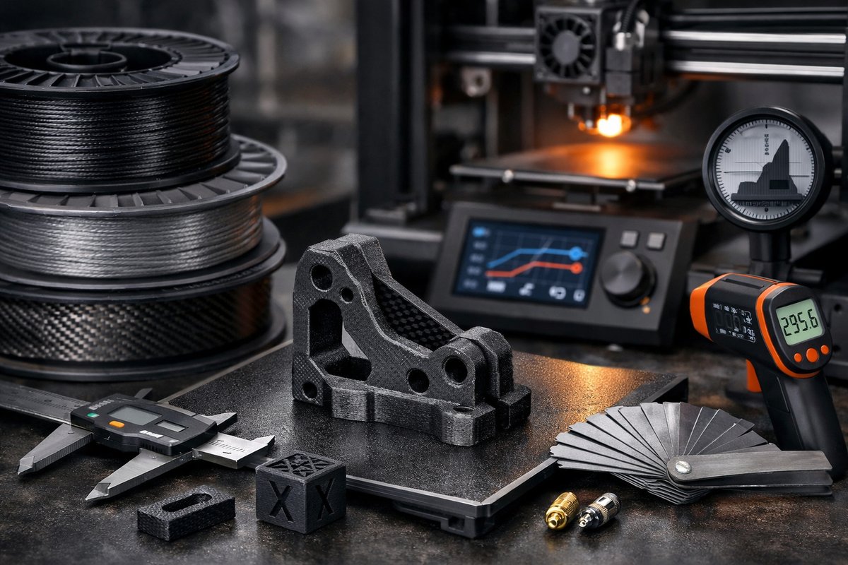
Discover how to take your fused deposition modeling (FDM) workflow to the next level with high-performance composite filaments and essential calibration tools. This hands-on guide walks you through every step-from choosing the right filament to fine-tuning printer settings-so you can achieve stronger, more precise prints with minimal trial and error.
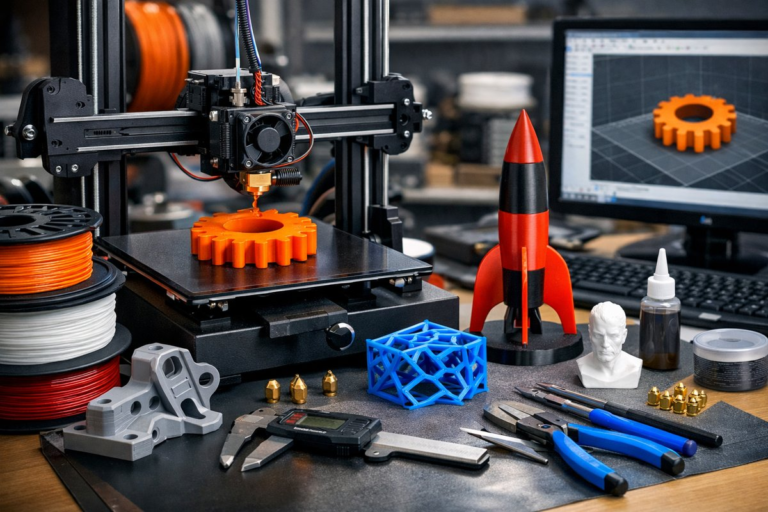
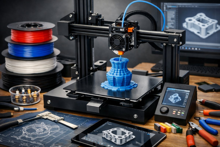
Fused deposition modeling (FDM) remains the most accessible and versatile form of desktop additive manufacturing. By extruding thermoplastic filament through a heated nozzle, FDM printers build parts layer by layer, transforming digital CAD designs into physical objects in mere hours. While PLA and PETG filaments are often the go-to choices for newcomers, exploring advanced materials-such as carbon fiber reinforced PLA or nylon blends-can unlock a new realm of strength, stiffness, and surface finish. This guide focuses on one specific FDM approach: printing with carbon fiber composite filaments on a properly calibrated machine.
First, let’s clarify why carbon fiber reinforced filament is so appealing. Tiny chopped fibers embedded in the polymer matrix increase tensile strength and reduce part weight. The result is a part that resists bending better than standard PLA, yet still prints at moderate temperatures. Carbon fiber blends also exhibit minimal warping, making them relatively user-friendly compared to pure nylon. You can create functional prototypes, brackets, jigs, and end-use components that were once impractical with consumer-grade machines.
Begin by selecting the right spool. A quality carbon fiber filament typically lists a diameter tolerance of ±0.02 mm. The most common diameter is 1.75 mm, compatible with nearly all desktop FDM printers. Look for filaments packaged with desiccant packs or stored in resealable, moisture-barrier bags. Moisture in the filament can lead to bubbles, poor layer adhesion, and reduced mechanical performance.
Next, inspect your nozzle. Standard brass nozzles wear down quickly when printing composite materials because the microscopic fibers abrade the brass. Instead, install a hardened steel or ruby-tipped nozzle. These nozzles maintain their orifice size over hundreds of hours, ensuring consistent flow rates and accurate layer deposition. A 0.4 mm hardened steel nozzle is a versatile choice, offering a balance between detail and print speed.
Calibrating the extruder is the third critical step. Even a slight over-extrusion or under-extrusion can compromise surface quality and part strength. Use a digital caliper to measure a marked length of filament before and after commanding the extruder to feed 100 mm. Adjust the E-steps value in your printer’s firmware or slicing software until the actual extrusion matches the intended length. This one-time calibration sets the foundation for dimensional accuracy in every print.
Bed preparation also influences first-layer adhesion and part flatness. A heated build platform set to around 60-70 °C works well for carbon fiber PLA. Clean the surface with isopropyl alcohol to remove oils and dust. If you’re using a glass bed, a thin coat of standard adhesive-such as a glue stick or hairspray-provides reliable grip without damaging the model. For build plates with a textured spring steel sheet, you may be able to print directly without extra adhesive, depending on your filament brand.
With hardware prepped, move on to slicer settings. In your preferred slicing software, set the nozzle temperature between 210 °C and 230 °C. Start at a middle temperature-220 °C-then adjust up or down in 5 °C increments to fine-tune layer bonding and surface smoothness. Cool the part with a 40-60% fan speed after the first few layers. Excessive cooling can cause layer separation with composite filaments, while insufficient cooling can lead to sagging on overhangs.
Layer height directly impacts both print quality and mechanical strength. A layer height of 0.2 mm works well with a 0.4 mm nozzle, delivering good resolution without overly long print times. Thicker layers (0.3 mm) can enhance strength by increasing the thickness of each deposited strand, but may reveal more visible layer lines. Your choice will depend on whether strength or aesthetics is the higher priority for your application.
Retraction settings help eliminate stringing and oozing, especially on models with frequent travel moves. For carbon fiber blends, a retraction distance of 4-6 mm at a speed of 40-60 mm/s is a solid starting point. Conduct a stringing test-two towers separated by 50 mm-and tweak distance or speed until only minimal wisps appear between towers.
Once you’ve dialed in the primary settings, consider enabling structural enhancements. Infill patterns such as gyroid or cubic offer balanced strength in multiple directions, while grid infill is faster to print but may concentrate stress along straight lines. A 20-30% infill density typically suffices for functional prototypes, but heavier-duty parts can require 40-60%. For maximum strength, experiment with a 100% infill at slower speeds, taking advantage of the filament’s reinforcing fibers.
Stiff shells around the infill further increase rigidity. Setting two or three perimeter walls-combined with a 0.8 mm or 1.2 mm shell thickness-produces a tough exterior that resists impact and vibration. These stiffer walls also help bridge gaps and overhangs by providing a solid foundation for subsequent layers.
When the slicer job is configured, start your print. Keep an eye on the first few layers to ensure proper adhesion and uniform filament flow. If the filament seems too thin or too thick, pause the print and adjust the Z-offset or hotend temperature accordingly. Once the print progresses beyond the first 10 mm, you can step back but remain within earshot to detect unusual sounds indicating nozzle clogs or filament slip.
After the print finishes, let the part cool on the bed. Rapid removal can warp the corners, so wait until the build plate temperature drops below 40 °C. Use a flexible scraper or the bending action of a spring steel sheet to gently release the part without risking damage. If you used a glass bed, warming it slightly above room temperature can also help the model detach cleanly.
Post-processing can elevate your carbon fiber prints from functional prototypes to showcase-worthy demonstrations. Light sanding with 220- to 400-grit sandpaper removes visible layer lines, while polishing compounds restore a subtle sheen. If you plan to paint the part, fill minor gaps with a thin primer filler, then apply a couple of coats of acrylic or automotive primer before finishing with your desired color.
Troubleshooting tips keep your workflow smooth. If you notice poor layer adhesion, increase the nozzle temperature by 5-10 °C or slow the print speed by 10-20 mm/s. For under-extrusion, check for filament grinding at the drive gear, and ensure the feeder tension is neither too loose nor too tight. For frequent nozzle clogs, consider printing a few dry filament purge lines before each job, or installing a nozzle cleaning kit with fine needles to remove trapped particles.
Beyond carbon fiber, your calibrated machine can handle other composite materials-wood-filled PLA for a natural grain finish, metal-filled filaments for ornamental applications, even flexible TPU for custom gaskets. The secret is to adjust your hardware and slicer settings just as thoroughly as you did for carbon fiber PLA. Each new material will shape its own sweet spot of temperature, speed, and cooling.
In summary, mastering a single FDM technique begins with high-quality filament, hardened hardware, and meticulous calibration. By following these steps-from filament selection and nozzle upgrade, through slicer tuning and post-processing-you’ll produce parts that combine both precision and performance. With each successful print, your confidence will grow, inviting you to explore ever more advanced materials and applications. Layer by layer, you’ll transform abstract CAD models into reliable, ready-to-use components-literally building your expertise one filament at a time.