Location
Mount Vernon, WA 98274

Location
Mount Vernon, WA 98274
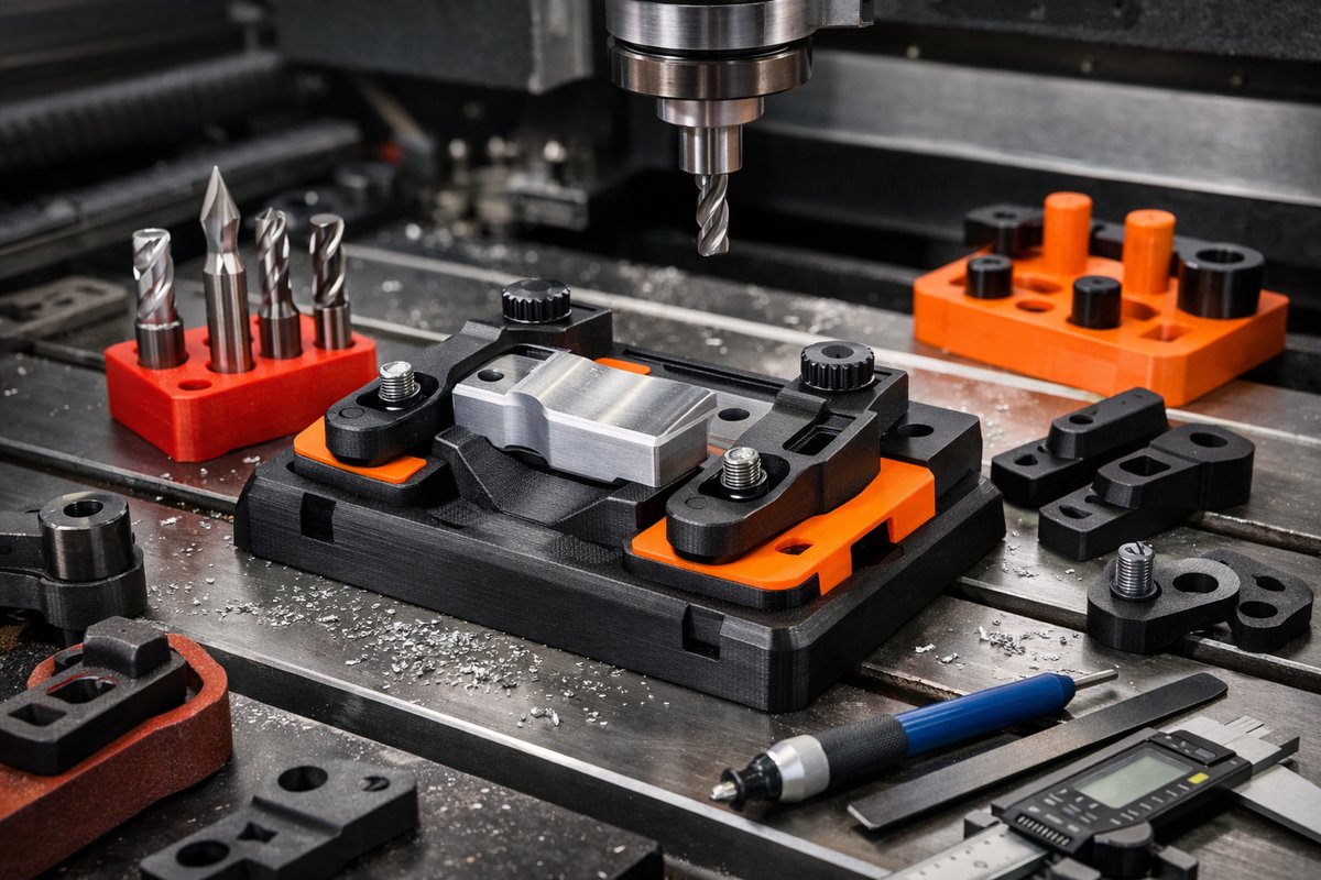
Harness the versatility of FDM 3D printing to create custom jigs and fixtures that streamline your CNC machining process. This guide walks through design principles, print settings, post-processing, and seamless integration with end mills and hold-down clamps to achieve repeatable, high-precision results.
Every CNC project begins with the right support: a jig or fixture that holds your workpiece steady, aligns it precisely, and prevents chatter or movement under the cutting forces of end mills. Traditionally, these components have been handcrafted from hardwood or machined from metal-materials that demand time, material costs, and effort to shape. But what if you could simply design that same jig in CAD, hit “print,” and have a durable, custom fixture ready in hours? Fused Deposition Modeling (FDM) has matured into a reliable workhorse for hobbyists and professional shops alike, offering a low-barrier path to produce strong, purpose-built jigs that integrate seamlessly with your CNC router or mill.
From the moment you sketch out the first mounting hole to the final mill-ready trimming, this guide outlines the additive-to-subtractive workflow. You’ll learn how to choose filament and nozzle size for best strength, orient parts to maximize stiffness, dial in layer height for flat surfaces, and prepare printed parts for hold-down systems. We’ll introduce tools that elevate your printed fixtures into precision-machining assets-carbide end mills to refine critical edges, digital calipers to confirm tolerances, and specialized clamps designed to grip plastic components without damage.
Bold intentions yield bold results. By the end of this walkthrough, you’ll have a toolkit of strategies and components that turn a block of filament into a fixture as capable as any milled jaw or keyed plate. Ready your CAD software and calibrate your printer – a new era of jig-building is just one creative fusion away.
Designing for Strength and Precision
In a subtractive shop, custom jigs often see contact with side loads and downward thrusts from end mills. When you design a printed fixture, think in three dimensions: internal ribbing raises stiffness, filleted corners disperse stress, and strategically placed holes lock down each axis. Start with a basic plate that matches the outline of your spoilboard or machine bed, then add locating pins or cutouts keyed to your table’s T-slot pattern. Use generous radii on corners to prevent stress concentrations when you tighten clamps.
Create pockets where you’ll insert brass or steel dowel pins to reinforce repeated clamping cycles. If you anticipate heavy milling passes, incorporate integrated channels for M-strap hold-down straps or toggle clamps. The goal is a design that balances material use with rigidity; walls of 3 to 5 millimeters paired with 50-75 percent infill often deliver a perfect blend of strength and print speed. Lastly, export your design as an STL, then visualize the part in your slicer’s preview to verify layer continuity and support placement.
Dialing in Print Settings
The mechanical performance of a printed jig depends on four key slicer settings: nozzle diameter, layer height, infill pattern, and print orientation. A 0.4 millimeter nozzle strikes an ideal compromise, producing walls that bond firmly without excessive print time. Drop your layer height to around 0.16 millimeter for a flatter top surface, especially if that face will mate against the spoilboard. Infill in a grid or gyroid pattern provides isotropic strength-critical when side loads from end mills push laterally.
Orient the print so that the main clamping face grows parallel to the build plate. This alignment means layers run perpendicular to the clamping force, minimizing delamination risk. If your jig features undercuts or overhangs, add minimal supports under those areas and trim away once the print cools. Print at temperatures recommended by your filament manufacturer, then let the part rest for an hour to relieve internal stresses before any finishing.
Post-Processing for Perfect Flatness
Even the best-tuned print can show slight surface irregularities. A few minutes of light sanding or a swipe with a sharp blade will shave high spots and bring a face into full contact with the spoilboard. For PLA fixtures, a damp cloth and fine-grit sandpaper reveal a smooth, lapped finish; for tougher materials like PETG or ABS, deburr edges with a utility knife and follow with an acetone vapor bath if you need super-flat surfaces.
Test the fit of locating features using digital calipers set to your target dimensions. If your jig includes channels for dowel pins, insert the pins and confirm they slide without play. Any wobble here will translate into chatter under the cutter, so tighten or re-print as needed. Once crisp accuracy is restored, you’re ready to bring the fixture to your CNC machine.
Aligning Jigs on the CNC Bed
Place your printed fixture onto the spoilboard and use the same locating features you designed-T-nut slots, dowel pins, or keyed edges-to lock the part into position. Insert strap clamps or toggle clamps into the integrated channels, applying even pressure across all points. A thin shim under the fixture can compensate for small height differences, ensuring that the top surface sits squarely in your machine’s Z-plane.
Before cutting, jog your CNC spindle to a corner of the jig face and bring down a feeler gauge or a corner of your gauge block set until you touch the surface. That becomes your Z0 reference. Then, move to a second point at the opposite end of the fixture to confirm consistent Z height-if readings differ, a slight angle in your printed part may require a fresh lapping run or a re-print with improved first-layer settings.
Choosing End Mills for Jig Trimming
In many cases, you’ll need to trim excess plastic or route channels for part contours once the jig is secured. A flat-nose carbide end mill (4 or 6 millimeter diameter) handles bulk removal quickly, while a small ball-nose cutter (2 millimeter) excels at smoothing corners and radii. Low flute counts (2 or 3) help evacuate plastic chips and prevent heat build-up.
Set conservative spindle speeds-under 12,000 RPM on most routers-paired with moderate feed rates so you don’t melt the plastic. If your machine supports climb milling, use that direction to achieve cleaner edges. Always test your toolpath on a spare printed jig before running it on your master fixture.
Integrating Digital Measurement
Precision is nothing without confirmation. A high-quality digital caliper ensures your printed fixture meets the original CAD dimensions before you mill. During the machining cycle, a dial indicator on your spindle can catch subtle run-out issues and confirm flatness across the jig face. Employ a tool-length sensor or gauge block method to automatically zero each end mill, reducing the chance of over-travel or undercut.
Beautifying and Protecting Your Jigs
Once your hybrid process proves reliable, you might consider adding identification labels or part-number engravings directly into the jig design for easier sorting in the shop. A quick dip in a food-safe lacquer or brush-on epoxy coats the surface, repels coolant or cutting fluids, and extends the fixture’s lifespan. Should the printed jig ever crack or wear beyond service, your digital files are ready to spit out a replacement in short order.
Long-Term Rewards of an Additive-Driven Shop
Shifting traditional jig-making from wood and metal into the realm of desktop FDM printing empowers one-off creativity. You trade labor hours for design time, yet gain a repeatable, shareable library of fixture files. Colleagues halfway around the globe can print duplicates for their own machines, standardizing workflows and slashing setup time on every project.
By combining the strengths of additive and subtractive manufacturing-rapid prototyping with grit and precision-you unlock new possibilities for complex parts, short runs, and ever-tighter tolerances. A 3D-printed jig that jaws your workpiece to perfect alignment today could evolve into tomorrow’s production fixture with only minor tweaks. All it takes is design forethought, tuned print settings, and the right set of tools-like properly chosen end mills and a reliable digital caliper-to bring your fixture from lines on a screen to rock-solid reality under the router bit.
Whether you’re chasing zero backlash, battling tool deflection, or simply striving for faster setups, additive manufacturing extends your subtractive toolkit in unexpected, rewarding ways. Give it a try on your next project, and watch how a swipe of filament transforms into the foundation of your most precise cuts yet.












