Location
Mount Vernon, WA 98274

Location
Mount Vernon, WA 98274
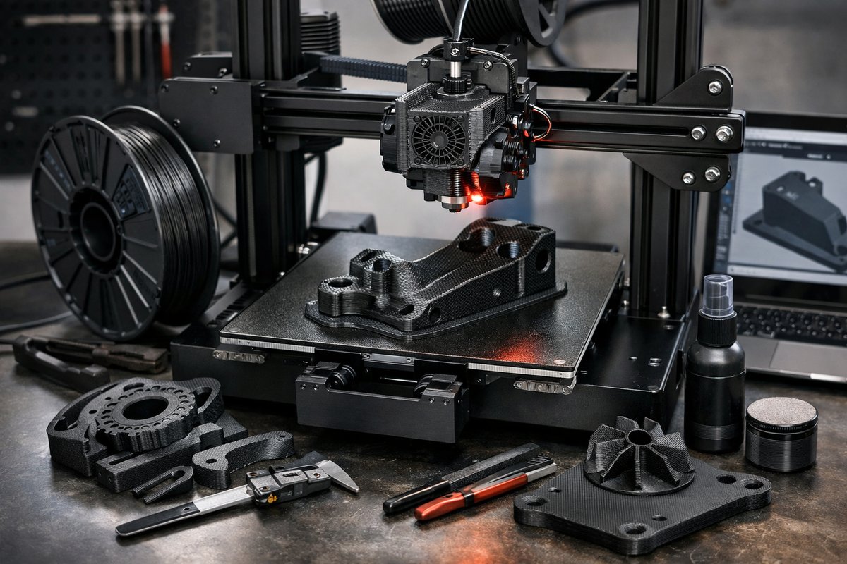
Explore how composite fused deposition modeling transforms desktop 3D printers into functional part factories. This guide reviews carbon fiber reinforced PETG printing, detailing the key components, settings, and post-processing steps to help you create durable, high-performance prototypes at home.
Additive manufacturing has come a long way from its early days of fragile plastic trinkets. Today’s fused deposition modeling (FDM) machines can handle composite filaments that blend standard thermoplastics with reinforcing materials like carbon fiber. The result is parts that resist bending, withstand higher temperatures, and deliver a surface finish reminiscent of machined components. This guide dives into the world of carbon fiber reinforced PETG printing, walking you through the hardware, materials, slicing strategies, and finishing tricks you need to produce sturdy prototypes that feel as if they were milled rather than extruded.
To begin with, composite filaments combine a base polymer-often PETG or nylon-with tiny fibers of carbon or glass. Those fibers crank up stiffness and reduce warping, but they also introduce abrasiveness that can damage standard brass nozzles. You’ll need a hardened steel or ruby nozzle to preserve precision over dozens of prints. An all-metal hotend capable of holding consistent temperatures around 240-260 °C is also essential, since composite materials require higher melt points. Many builders upgrade to a full-steel heatbreak and a hardened throat to avoid clogs when printing abrasive blends.
Bed adhesion takes on new importance when layering carbon fiber PETG. A spring steel build plate finished with a removable PEI sheet offers reliable grip without glue sticks or tapes. Heating the bed to 70-80 °C prevents the part edges from peeling, especially for larger models. A rigid, flat metal surface helps maintain first-layer consistency, while a flexible steel plate allows you to pop off parts once they cool, avoiding prying or damaging the print.
On the filament front, choose a reputable carbon fiber reinforced PETG spool rated for around 1 kg, with a 1.75 mm diameter tolerance of ±0.03 mm. Storing the spool in a resealable pouch with desiccant prevents moisture absorption, which can lead to stringing, bubbles, and reduced layer bonding. If your workshop humidity is high, a filament dryer or dry box ensures consistent extrusion throughout long print jobs.
Once your hardware is ready, it’s time to dial in slicing settings. Start with a 0.4 mm hardened steel nozzle and set the layer height between 0.2 and 0.3 mm for a balance of speed and detail. Increase wall thickness to at least 1.2 mm (three perimeters) to showcase the fiber reinforcement in the part’s structure. A slightly slower print speed-around 30-40 mm/s-gives the molten filament time to bond, so you don’t lose strength at bridges or overhangs. Retraction settings should be moderate (2-4 mm at 30 mm/s) to limit stringing without grinding fiber particles in the nozzle.
Temperature tuning is a critical step. Perform a temperature tower test: print a small calibration model with incremental temperature changes every 10 mm. Observe layer adhesion, surface smoothness, and bridging performance. Most carbon fiber PETG blends perform best between 240 °C and 255 °C on the hotend and 75 °C on the bed. Use a gentle cooling fan at 20-30 % after the first few layers to preserve overhangs while preventing the PETG from sagging.
For challenging geometries-like internal channels or lattice infill-consider enabling vertical shells and concentric infill patterns. The added perimeter layers improve stiffness along the outer surfaces, while concentric infill transfers load paths more evenly. When creating functional prototypes such as drone arms, brackets, or custom fixtures, these strategies deliver parts that resist twisting and flexing under real-world loads.
After printing, post-processing can accentuate strength and aesthetics. Lightly sanding with 200-400 grit wet-dry sandpaper smooths layer lines; apply even pressure to avoid gouging the carbon fibers. Mask and spray a thin coat of matte epoxy primer to fill micro-gaps and seal exposed fibers for a uniform finish. For extra chemical resistance or a polished look, a clear aerosol resin sealer adds a glossy protective layer that also strengthens the outer surface.
Troubleshooting composite FDM is straightforward once you understand the key variables. If your prints show layer separation or delamination, raise the hotend temperature in 5 °C increments or reduce print speed. Stringing indicates moisture in the filament or too much retraction-dry the spool and reduce the retraction distance. If the nozzle clogs, purge with a cleaning filament rated for composites and inspect the hotend for wear; replace the nozzle every 500 g of abrasive materials.
Safety is another critical consideration. Wear a respirator or mask rated for fine particulates when cutting, sanding, or vapor smoothing composite prints, since carbon fiber dust can irritate skin and lungs. Good ventilation helps disperse any fumes that arise when heating high-temperature thermoplastics.
By mastering carbon fiber reinforced PETG printing on your desktop FDM setup, you unlock a world of functional, industrial-grade prototypes. Whether you’re crafting robotics components, jigs for workshop fixtures, or strong decorative pieces with a unique matte-black finish, composite FDM brings a level of durability and aesthetic appeal that standard filaments can’t match. With the right nozzles, bed surface, filament storage, and slicing profile, you’ll turn your digital designs into real-world parts capable of handling tough mechanical challenges.
Now that you’ve seen how hardware choices, filament quality, and slicing strategies work in concert, you can tackle your next project with confidence. Embrace the learning curve, keep notes on your temperature and speed tweaks, and experiment with infill patterns to discover how carbon fiber reinforcement can elevate your additive manufacturing to professional standards. Your next prototype could be more than a proof of concept-it could be a load-bearing, production-ready component printed right at home.