Location
Mount Vernon, WA 98274

Location
Mount Vernon, WA 98274
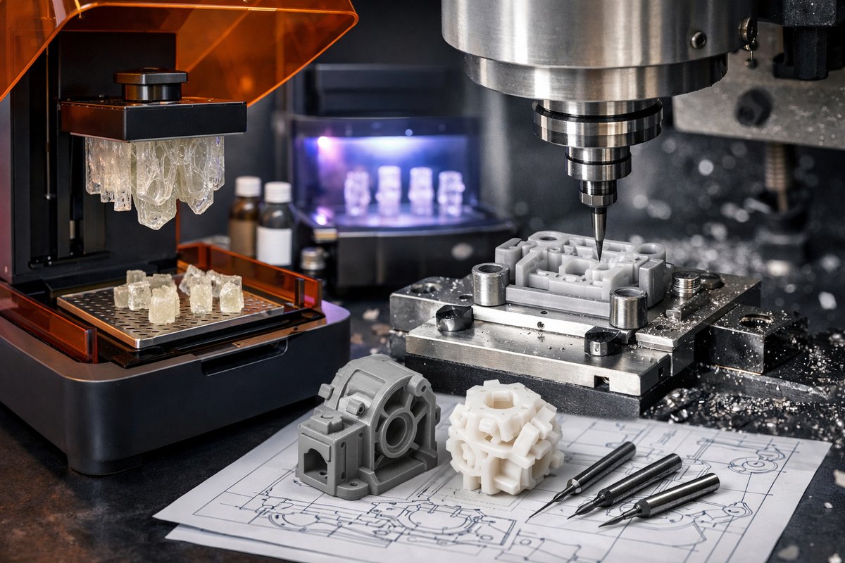
Dive into a step-by-step exploration of SLA (Stereolithography) additive manufacturing paired with CNC micro-milling to achieve high-detail polymer parts. Learn resin selection, print orientation, post-curing best practices, and micro end mill finishing techniques that elevate your first prototype to production-ready hardware.
Additive manufacturing often dazzles with complex geometries, but raw prints can fall short when it comes to tight tolerances or mirror-smooth surfaces. This guide shows how to harness SLA resin printing for fine features, then follow up with CNC micro-milling to reach dimensional precision and refined finishes. By blending vat polymerization and subtractive machining, you’ll uncover hidden details and turn layered artifacts into professional-grade parts.
We’ll cover: resin selection and safety, print orientation and support strategy, post-print wash and UV cure, jigging parts in a desktop CNC router, choosing the right micro ball nose end mill, and machining parameters that preserve delicate features. Read on to discover how each step builds on the last, creating synergy between two manufacturing worlds.
SLA resins vary in viscosity, Shore hardness, and UV reactivity. Standard photopolymer resins (viscosity ~3,000 cP) deliver crisp details at 50 micron layers, ideal for jewelry or small form-factors. Tough resins offer higher impact resistance for functional prototypes, while high-temp variants withstand elevated environments. Before opening a resin bottle, equip yourself with nitrile gloves, chemical-resistant safety glasses, and a lab-grade respirator if you’re working in a poorly ventilated space.
Steps:
Keep a small funnel and a dedicated resin filter on hand to return leftover resin to the bottle once printing starts, minimizing waste and contamination.
Orientation dramatically affects surface finish and post-print work. Aim to minimize support contact on critical faces. A 30-45° tilt reduces overhangs and distributes support anchors along edges rather than flat faces, cutting cleanup time. In your slicer, set support density between 10 and 20 percent; higher densities may hold features more securely but leave larger marks.
Key settings:
After slicing, preview the support distribution. If a thin wall shows large flat contact points, add custom tree supports or break that wall into multiple parts for assembly.
Fresh prints emerge sticky and fragile. A two-stage wash ensures residual resin is removed without soaking the part’s internal cavities. First, submerge the build in a bath of 90 percent isopropyl alcohol for 2-3 minutes with gentle agitation. Then move the part into a second IPA bath for a quick rinse.
Shake off excess liquid, pat dry with a lint-free cloth, and place the parts in a UV curing station. Cure for 10 minutes per side (rotate 180° halfway through) at 405 nm light. Proper curing locks in dimensional stability and improves hardness-critical before any machining passes. Avoid over-curing; parts can become brittle above 20 minutes total, risking cracks under cutting loads.
With crisp, cured prints in hand, the goal is to reference true datums for machining. A small machinable fixture plate or vacuum base works well on a desktop CNC router. Align the primary datum face against an aluminum stop block, and clamp gently to avoid crushing delicate ribs. If you lack a vacuum table, two parallel clamps with sacrificial PVC or nylon washers ensure even pressure distribution.
Always verify part flatness at the fixture interface using a dial indicator. Microns of misalignment translate into visible surface waviness after milling. Use a digital probe or an edge finder to establish X-Y zero at your chosen corner, then set Z zero by touching off a depth-micrometer tool or a paper shim.
Micro milling relies on carbide end mills from 0.5 to 2 mm diameter. A ball nose profile excels at contour finishing, following curved surfaces without leaving scallops that require manual sanding. For SLA polymers, choose a two-flute carbide bit with a high helix angle (35°-45°) to clear chips quickly and prevent heat buildup.
Recommended parameters for a 1 mm ball nose:
Use canned air or a gentle mist coolant to clear chips-avoid flooding the resin part with liquid, which can soften details.
Begin with roughing passes only if large volumes need removal-though for most SLA parts, roughing isn’t necessary. Proceed directly into a fine finishing path. In your CAM software, generate parallel or pencil-path toolpaths along critical edges. Keep passes shallow to prevent chatter and use climb milling on convex features to enhance surface smoothness.
After milling, inspect with a 10× loupe to identify any remaining ridges. For ultra-fine polish, gently touch high spots with 600-grit wet-dry sandpaper on a flat block, followed by 1000-grit for luster. Finish with a light buff using a polishing compound and a soft wheel if the design demands a glossy look.
This workflow shines when you embed metal inserts or mating features. Till resin parts exhibit tight bores, downsize the CAM path by 0.1 mm when planning pockets for brass threaded inserts. Press-fit anchors into the semi-cured resin before the final UV cure, then mill the top surface flat to reveal flush insert rings. The result: robust joints suitable for repeated assembly cycles.
Tip: Use a two-component epoxy with low shrinkage to secure inserts, curing at room temperature overnight for best strength. Protect mating surfaces during epoxy cure with waxed paper to prevent accidental gluing of fixtures.
By fusing SLA printing’s capacity for intricate forms with CNC micro-milling’s precision, you’ll unlock part qualities previously reserved for injection molding. Prototype enclosures, optical mounts, medical models, and more come to life faster, with superior fit and finish. Ready to merge additive freedom with subtractive accuracy? Gather your tools and start exploring the micro geometry that lies beyond the printer’s native limits.












