Location
Mount Vernon, WA 98274

Location
Mount Vernon, WA 98274
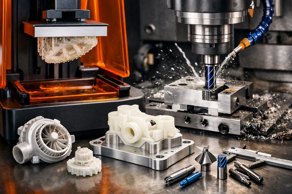
Discover how to fuse the precision of SLA resin 3D printing with the power of CNC milling to produce parts that marry fine detail with structural accuracy. This guide walks you through materials, machine setup, post-processing, and finishing steps-complete with tips on selecting specialized end mills and router bits to take your prototypes from concept to polished reality.
Additive manufacturing shines when intricate geometry meets rapid iteration. Yet even the smoothest layers of a resin-cured model can lack the crisp edges and high-tolerance surfaces needed for jigs, tooling masters, or snap-fit enclosures. That’s where subtractive finishing comes in. By combining stereolithography (SLA) 3D printing with a desktop CNC machine, you unlock a hybrid workflow that leverages the best of both worlds: the organic freedom of resin printing and the exacting power of precision milling.
Understanding the Hybrid Approach
At its core, this technique splits production into two phases. First, SLA builds the bulk of your design layer by layer, capturing curves, undercuts, and fine detail down to a few microns. Then, a CNC router or mill carves critical faces, bores, or mounting features to exact dimensions. You might print a complex housing with internal channels and later machine flat mounting surfaces or threaded bores that demand tight tolerances.
Why it works: SLA’s photopolymer layers bond fully in liquid resin vats, producing models with smooth surfaces straight off the printer. But even top-end SLA units can show fine stair stepping or slight dimensional drift over large spans. When you transfer that part to a CNC toolpath, you remove a thin skin-often less than half a millimeter-revealing a geometry locked to your machine’s dialed-in origin and cutting tool.
Essential Equipment and Materials
You’ll need two primary platforms: an SLA 3D printer and a desktop CNC mill or router. Choose an SLA unit with a reliable vat leveling system and UV curing station for best results. On the machining side, a desktop CNC kit with an aluminum end-mill spindle and rigid frame will handle resin without chatter.
Materials play a key role. For printing, use an engineering-grade resin formulated for dimensional stability and low shrinkage. Standard clear or gray resins work, but look for ones labeled “high-precision” or “low-warp.” After printing, rinse in isopropyl alcohol, cure under UV, and let the part rest to relieve internal stresses before machining.
On the CNC side, select carbide end mills with a small diameter (2 mm or 3 mm) for fine detail, plus a 4 mm or 6 mm bit for bulk stock removal. A few ball-nose cutters help with smooth transitions. Finally, secure your print on the CNC bed using double-sided tape or a light adhesive-resin can cling well to sacrificial plywood or MDF spoil boards.
Step-by-Step Workflow
1. Model Preparation: In your CAD software, split the design into two zones: the free-form section for SLA and the critical faces for CNC. Export each as separate STL files. In the CAM environment, assign printing orientation to minimize support marks on CNC faces, then generate CNC toolpaths for the machined surfaces.
2. Printing: Slice the free-form part with supports placed away from the future machining faces. Print at a layer height of 25-50 microns for optimal detail. Once complete, remove supports, rinse the model in 90%+ isopropyl alcohol until clear, and post-cure in a UV chamber for at least 10 minutes.
3. Registration and Fixturing: Mount the cured print on the CNC bed. Use alignment pins or printed witness marks that seat into a matching jig on the spoil board. Zero the CNC axes on one corner of the printed block, then set the Z-height using a paper touch or auto-tool-height probe if available.
4. Rough Machining: Start with a larger end mill (4 mm-6 mm) to skim the walls, removing 0.2-0.3 mm of resin per pass. Keep feed rates moderate (500-800 mm/min) and spindle speeds high (10,000-12,000 RPM) to avoid melting the resin. Clear chips frequently to prevent dragging or heat buildup.
5. Precision Finishing: Swap to a 2 mm to 3 mm carbide end mill or a ball-nose cutter for the last 0.1 mm of material. Slow down to 300-500 mm/min and maintain a shallow depth of cut (0.05-0.1 mm). This slice leaves mirror-smooth surfaces that match your CAD model within a few microns.
6. Inspection and Assembly: Clean off any remaining dust or chips with compressed air or a brush. Measure critical dimensions with a digital caliper or micrometer. If you designed threaded holes, insert the correct tap and cut threads carefully, using lubricant. Finally, assemble against mating parts and test fit to confirm tolerances.
Fine-Tuning Your Setup
Success hinges on calibration. Regularly check your printer’s Z-offset and ensure your CNC’s belt tension and spindle run-out remain within spec. Replace worn end mills once performance drops; a dulled carbide bit can tear resin rather than cut it. Experiment with different resin brands, too-some handle end-finishing with less chipping.
A key trick is to adjust your CAM’s allowance for resin shrinkage. If you notice uniform undersizing after curing, increase your finish offset by 0.1-0.2 mm in X and Y. That way, your CNC trim cut restores ideal dimensions every time.
Creative Applications
This hybrid workflow shines across disciplines. Toolmakers can prototype drill jigs with integrated vacuum channels, then machine datum faces for absolute alignment. Scale-model builders can print detailed terrain, then route mounting holes for LED strips. Jewelry designers produce organic forms on SLA and finish flat bezel edges to fit gemstones exactly.
One standout use case: functional spring-clip assemblies printed in durable resin, then milled at contact surfaces for wear resistance. The result is a flexible hinge that snaps perfectly and mates with standard hardware. Industrial R&D labs adopt this approach to speed design-verification cycles, shaving days off lead times compared to fully machined prototypes.
Troubleshooting Common Issues
Warp orCurling: Ensure even support distribution and avoid overcured edges. If layers lift, increase the number of raft layers or adjust exposure times.
Chatter Marks: Lower spindle speed, increase feed, or switch to a light-cutting ball-nose bit.
Dimensional Drift: Account for resin shrinkage in your CAM allowance. Let prints rest overnight before machining to stabilize.
Chip Adhesion: Resin chips can stick to tools at high temperatures. Drop depth of cut or add a short dwell at each pass to clear chips.
No-Go Fits: Check your toolpath zero reference. A slight misalignment in X or Y can shift the entire machining zone. Use corner markers or test cuts on scrap resin blocks to confirm accuracy.
Building Your Workshop
Start small with a compact SLA printer and an entry-level CNC mill. As you gain confidence, upgrade to a vacuum table for better hold-down or invest in advanced software that seamlessly imports STL scans into machining paths. Add a digital microscope to inspect tool wear and surface finish at high magnification.
Long-term, you can expand into multi-axis hybrid machines that switch automatically between laser curing and spindle milling. But the fundamental secret remains the same: marry the fast geometry capture of SLA with the pinpoint control of subtractive cutting. The marriage of addition and subtraction elevates both methods.
A New Standard in Rapid Prototyping
By blending SLA 3D printing with CNC finishing, you’re not just stacking up layers; you’re carving out precision. This hybrid path unlocks parts that once required expensive tooling, bridging the gap between concept sketches and production-ready components. With the right resin, end mill, and a methodical workflow, you can push prototypes to production with confidence-knowing each surface meets your exacting standards.
Embrace this journey of subtraction from addition and discover the freedom of a workshop where every pass, every cut, and every cured layer brings your vision into sharper focus.












