Location
Mount Vernon, WA 98274

Location
Mount Vernon, WA 98274
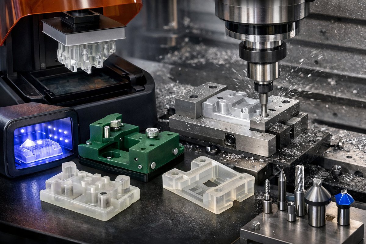
Unlock the synergy between SLA 3D printing and CNC machining by crafting high-precision jigs that streamline your workshop workflows. This guide dives into the resin-based process, post-curing best practices, and how to integrate end mills and router bits for flawless surface quality.
Additive manufacturing has exploded onto the workshop scene, offering a fresh path to parts that once demanded long machine setups and expensive tooling. Among the many technologies available, stereolithography (SLA) stands out when extreme detail, tight tolerances, and smooth surfaces are critical. Instead of building layer by layer with plastic filament, SLA cures liquid photopolymer resin with a focused light source, achieving feature resolutions that rival fine injection molding. In this guide, we’ll walk through the complete workflow: from preparing a model in slicing software to post-processing prints, and finally integrating your printed jig or fixture into a CNC setup using precision tools like end mills and router bits.
Before diving into the steps, it helps to understand why SLA is a powerful choice for creating precision jigs. The process begins with a vat of resin-an engineered photopolymer loaded with additives for strength, flexibility, or heat resistance. A light source, typically a laser or an LCD screen, traces each cross section of your model on the resin surface, triggering a chemical reaction that solidifies the material. Once one layer cures, the build platform lifts, allowing new resin to flow underneath. This cycle continues until the entire part emerges. The result is a part with layer heights as low as twenty-five microns, virtually invisible layer lines, and the ability to capture intricate details such as internal channels or micro holes. For shop fixtures where flatness and fit matter, SLA can shave hours off manual machining and reduce material waste.
Gathering Your Tools and Materials
• SLA Resin 3D Printer: A desktop machine with a stable Z-axis and consistent light source gives the best repeatability.
• Engineering-Grade Tough Resin: Choose a formula rated for dimensional stability and mechanical strength, especially if your jig will clamp parts under load.
• Isopropyl Alcohol (IPA): 90% or higher concentration for washing away uncured resin.
• Post-Cure UV Chamber: Ensures complete polymerization to unlock full mechanical properties of the print.
• Digital Calipers: Essential for measuring critical dimensions on test prints and verifying fit.
• Premium Carbide End Mills: A selection of flat and ball-nose cutters to fine-tune hole diameters or smooth mating faces.
• CNC Router Bit: Use a 1/8″ or 1/4″ straight bit for trimming edges or adding registration features.
Step 1: Designing for Accuracy
Begin in your CAD environment by modeling the jig around the precise geometry of the workpiece. Include alignment pins, clamping channels, or reference surfaces that mate directly to your part. Pay attention to tolerances: consider adding a small clearance of 0.1 mm to 0.2 mm for sliding fits so printed parts aren’t too tight. When designing bosses or standoffs, keep their cross sections at least 1 mm thick to ensure strength. If you plan to insert metal pins or bushings later, model these holes slightly under size-CNC finishing will bring them to final diameter.
Export your model as an STL with high triangulation density to preserve curves. In your slicing software, orient the jig so its critical faces are as parallel to the build platform as possible. This reduces the need for support structures on functional surfaces and improves surface finish. Set layer height to 50 μm for a balance of print speed and detail. Adjust exposure times according to your resin manufacturer’s recommendations, and enable anti-aliasing if your machine supports it to smooth layer transitions.
Step 2: Printing and Washing
With your build platform leveled and resin vat topped off, start the print. Keep an eye on the first few layers to ensure good adhesion. Poor first-layer bond can introduce shifting, which ruins tolerance. Once printing completes, carefully remove the platform and shake off excess resin back into the vat. Submerge your part in an IPA bath and agitate gently for three to five minutes. Ultrasonic cleaners can speed up this wash and help dislodge resin in tight corners, but avoid extended wash times that may leach resin out of features.
After washing, let the part air dry in a dust-free environment. Rock the part back and forth to shed any remaining liquid from cavities. A fully dry part will cure more evenly under UV.
Step 3: Post-Curing and Inspection
Position the dried print in your UV chamber, aiming LEDs at any overhangs or recesses that didn’t see full light exposure. A ten-minute cycle is often sufficient when the part is rotated every two minutes-this ensures every surface reaches the required energy dose. Some UV chambers include heat, which can toughen the resin further; follow resin guidelines to avoid warping delicate features.
Once cured, measure key dimensions with digital calipers. Verify hole diameters, slot widths, and flat face heights against your CAD model. Note any deviation. Minor shrinkage-often between 0.1 % to 0.3 %-is typical. Record these offsets for future prints or compensate in your slicing settings.
Step 4: CNC Finishing for Perfect Fit
Even the finest SLA prints benefit from a touch of machining when tight fits or ultra-smooth surfaces are required. Mount the jig on your CNC machine table, using vacuum hold-down or double-sided tape on non-critical faces. Load a carbide end mill in the spindle: a 3 mm flat-bottom cutter works well for squaring faces or sizing slots. Program a shallow pass of 0.2 mm depth to skim the resin without chattering. A feed rate of 500 mm/min and spindle speed around 12,000 RPM gives a clean finish. For internal holes, swap in a 2 mm ball-nose cutter to avoid dog-legging. If you need crisp corner radii, combine a 1 mm end mill with a downward spiral toolpath to maintain stability.
Alternatively, use a handheld CNC router or a desktop benchtop mill for spot-facing and adding reliefs. A straight router bit lets you add cable channels or chamfers while preserving registration surfaces. Always air-blast the cut area to remove chips and prevent heat buildup. After machining, blow off any remaining debris with compressed air and inspect mating surfaces again with calipers.
Step 5: Assembly and Testing
With your jig machined to spec, insert any metal dowel pins, bushings, or fasteners into captured holes. Dry-fit your workpiece and verify alignment under light pressure. A feeler gauge can check for unwanted gaps. If you see misalignment, note whether it’s due to design error or print shrinkage. Adjust your CAD model accordingly and reprint a test piece. Over successive iterations, you’ll dial in offsets until the jig holds parts with repeatable accuracy.
Use the completed jig to guide end mill operations, drilling sequences, or polishing steps on your workpiece. The beauty of SLA-based fixtures is that you can rapidly prototype and iterate new clamping strategies without ordering custom steel tooling-often saving days of lead time and significant cost.
Bringing It All Together
Pairing resin 3D printing with light CNC finishing bridges additive and subtractive processes in one seamless workflow. By leveraging SLA’s high resolution and a few passes of a carbide cutter, you unlock a new level of precision in shop-made jigs and fixtures. The keys to success are thoughtful design for printing, meticulous post-processing, and controlled machining passes. Along the way, digital calipers and end mills become your trusted allies, ensuring each trial yields insights for the next iteration. Whether you’re a hobbyist outfitting a home workshop or a seasoned machinist streamlining production, this hybrid approach breathes fresh life into how we think about tooling.
Curiosity and patience drive mastery. As you experiment with different resin formulations, explore micro-bushing inserts, or refine toolpaths for resin substrates, you’ll discover fresh possibilities in quick-turn fixturing. The quiet discipline of subtractive adjustments complements the creative freedom of additive design. And when your shop lights dim, you’ll know these jigs carry the spirit of craftsmanship-part digital, part analog, and fully driven by the desire to make things precisely right.












