Location
Mount Vernon, WA 98274

Location
Mount Vernon, WA 98274
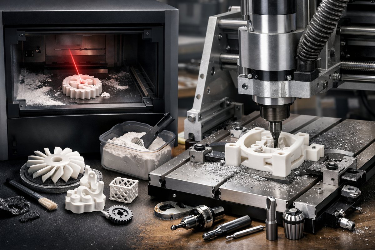
Discover how desktop selective laser sintering (SLS) combines with CNC milling to unlock ultra-precise polyamide parts. This guide reviews key process parameters, material handling, and essential tool choices-including ball end mills and open-frame routers-to help you integrate additive and subtractive workflows.
Subtractive machining has long been revered for its discipline and precision, but additive manufacturing continues to rewrite the playbook on complexity and customization. Desktop selective laser sintering (SLS) now brings powder-bed fusion within reach of small shops and makerspaces. By coupling SLS’s ability to produce durable, intricate polyamide parts with a CNC routing station, you can achieve dimensional accuracy and surface finishes that rival injection molding prototypes.
Understanding how to calibrate and control each stage is critical. In the SLS chamber, laser power, scan speed, and layer thickness define feature resolution, mechanical strength, and build reliability. Even minor deviations can warp lattices or leave voids in load-bearing sections. Once a part emerges from the sintering bed, the journey has only begun: depowdering, powder recovery, and infiltration set the stage for its final form. The CNC router then refines mating surfaces, bores precise holes, and polishes functional faces-transforming a rough print into a production-ready component.
So where should you start? First, choose the right polyamide powder. Medium-flow, fumed polyamide blends strike a balance between print reliability and mechanical properties. Look for materials certified for desktop SLS platforms, featuring consistent particle size distributions (20-100 microns) to minimize agglomeration and ensure even laser absorption. Store the powder in a humidity-controlled cabinet, because moisture uptake can lead to incomplete fusion and lower tensile strength.
Next, configure your desktop SLS machine. Pay close attention to the preheat temperature: set the chamber just below the polymer’s crystallization point to reduce warpage. Fine-tune the laser wattage and scanning velocity in small increments-start with manufacturer-recommended settings and test a calibration coupon that includes tensile specimens, thin walls, and lattice structures. Document each build’s parameters and inspect the coupon under magnification, noting any surface roughness or unmolten granules. This feedback loop will inform adjustments to hatch spacing and layer thickness (typically 0.08-0.12 mm for polyamide).
After the build completes, allow the chamber to cool gradually. Rapid temperature shifts can warp large parts. When the bed reaches roughly 50 °C, raise it slowly to room temperature before retrieving your print. Depowdering is easiest with an enclosed powder extractor or a soft brush and a gentle air stream. Collect the loose powder in a sealed bin for sieving and reuse-sorting through mesh screens (60-80 mesh) will remove oversized flakes or agglomerates before reblending with virgin powder.
Many applications benefit from infiltration. A thin layer of specialty resin, acrylic, or wax can seal surface pores, increasing tensile strength and smoothing the finish. Submerge the sintered part in the infiltrant under slight vacuum to encourage penetration, then allow excess to drain before post-curing under low heat. You’ll notice a noticeable improvement in stiffness and a slight darkening of the surface-this is normal and can be mitigated with light sanding if color consistency is critical.
With the part fully prepped, it’s time to bring in the CNC router. Mount the component in a custom fixture or a vacuum table, making sure its datum surfaces align precisely with your machine’s work coordinate system. A small touch probe or a repeatable mechanical stop can speed up alignment without risking damage to delicate features. Load the 3D scan or original CAD model into your CAM software and generate toolpaths that correspond to each finishing pass.
Selecting the right cutter is paramount. A 1/8″ carbide ball end mill excels at smoothing curved surfaces and blending transition zones. For detailed contours or small internal radii, swap to a 1/16″ tapered end mill. Keep spindle speeds between 12,000 and 18,000 rpm and feed rates around 1000-1500 mm/min to avoid melting the nylon. Utilize a high-pressure air blast or mist coolant to clear chips and maintain cutting temperature below the resin’s glass transition point.
Begin with a light roughing pass to remove superficial layers-0.2 mm depth of cut is usually sufficient. Inspect the component for chips or tool chatter, then proceed with a fine finishing pass of 0.05 mm to achieve surface roughness values under Ra 1.6 µm. The CNC operation reveals crisp edges on mounting faces, true bores for dowel pins, and perfectly flat sealing surfaces. Finally, remove the part from the router, deburr any sharp edges with a ceramic stone, and clean it in an ultrasonic bath to eliminate residual dust.
Integrating desktop SLS and CNC finishing unlocks a powerful hybrid workflow. You gain the freedom to explore organic geometries, internal lattices, and lightweight frameworks that only powder-bed fusion can deliver, while still achieving the mechanical precision and surface quality that milling provides. Whether you’re crafting functional prototypes, bespoke tooling, or low-volume production runs, mastering this process can cut lead times, reduce material waste, and elevate the reliability of each part you produce.
The key to success lies in iterative experimentation: track every build parameter, refine your CNC toolpaths, and maintain meticulous records of material batches. Invest in quality peripherals-digital calipers, probe kits, end mill sets, and proper powder handling equipment-and you’ll see steady improvements in part consistency and machine uptime. And as you gain confidence, start pushing the limits: combine multi-axis CNC operations with gradient structures in your SLS designs, or explore dual-material infiltration for localized reinforcement.
In the end, hybrid manufacturing is more than just a technical hack; it embodies the spirit of additive plus subtractive synergy. It demands patience, attention to detail, and a willingness to learn from each cycle. Yet the rewards-a fully realized component that meets tight tolerances, withstands demanding loads, and carries surface finishes destined for end-use-make every pass of the laser and every turn of the cutter worth the effort. Embark on your own desktop SLS and CNC journey, and you’ll discover new dimensions of precision that subtraction alone could never reveal.












