Location
Mount Vernon, WA 98274

Location
Mount Vernon, WA 98274
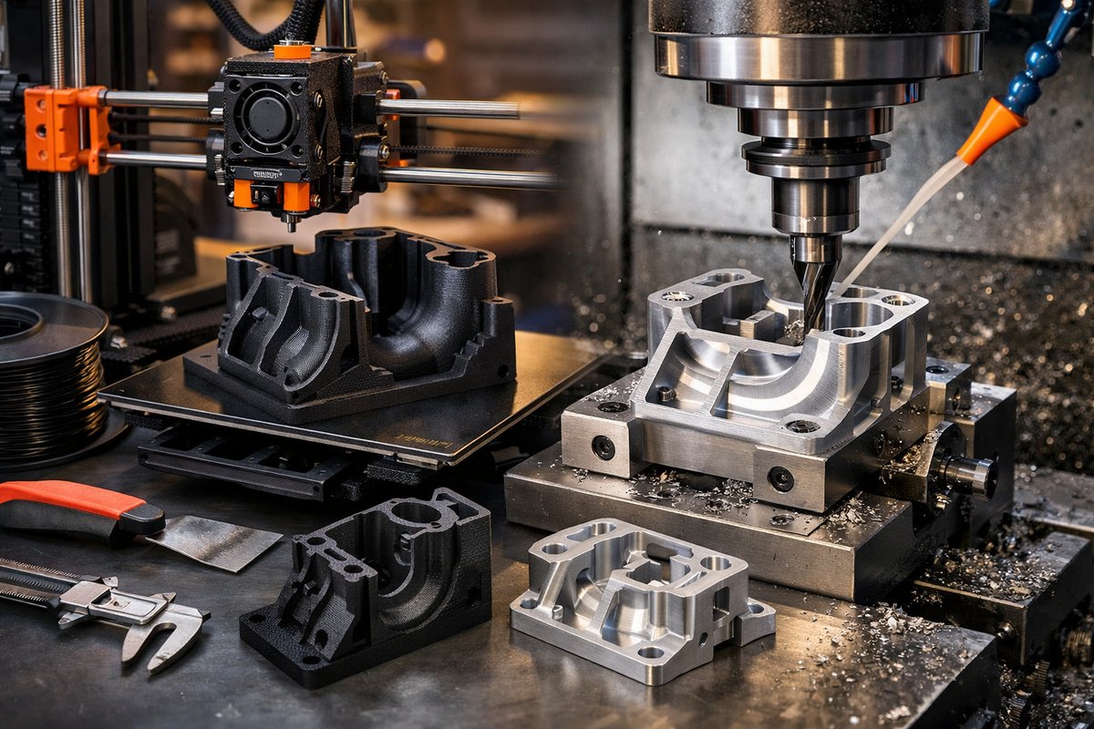
Discover a step-by-step guide that combines FDM 3D printing with CNC finishing to achieve parts with both complex geometry and tight tolerances. Learn how to design, print, and machine features for prototypes, fixtures, and functional components with industrial-grade precision.
Subtractive and additive manufacturing each have unique strengths. Additive methods excel at complex internal channels, organic shapes, and rapid prototyping, while subtractive machining carves crisp edges, precise hole patterns, and smooth surfaces. By pairing FDM 3D printing with a desktop CNC router or mill, you can tap into both realms-sustainably building up geometry layer by layer, then refining critical faces, pockets, and mounting points through controlled material removal.
Start with a project that benefits from hybrid precision. Imagine a custom fixture plate featuring internal cable channels and an accurately positioned mounting boss. In CAD, model the full shape, including expanded tolerances on mounting holes that the CNC finish will later dial in. Export your part as an STL and consider how each feature will translate through the print and the toolpath of the end mill.
Next, optimize your slicing parameters. Use a layered height between 0.2 mm and 0.3 mm for a good balance of surface quality and build speed. Select a reliable PETG filament-preferably a recycled or bio-blend material-to support sustainability goals. Configure 3 perimeters and a 20% grid infill for stiffness, and disable supports on surfaces destined for CNC finishing to save time removing artifacts.
Upgrade your printer with a hardened steel nozzle for composite or fiber-reinforced filaments. This ensures consistent performance when using abrasive materials that can accelerate wear on a standard brass nozzle. Level the build plate carefully and activate a properly tuned bed-adhesion method, such as a PEI sheet or adhesive stick, to hold the part against tool-induced vibrations during finishing.
Once the print is complete, inspect critical faces. File away minor stringing or burrs that might prevent accurate zeroing on the CNC machine. Clean the build plate and secure the part in a low-profile vise or with double-sided tape on the CNC router table. Use a digital probe or a touch plate to establish the XY origin at the corner of a printed datum or test coupon. This step anchors your toolpaths to the exact location of printed features.
Prepare your finishing toolpaths in CAM software. Begin with a roughing pass using a 1/8″ two-flute carbide end mill at a shallow depth of cut-0.5 mm per pass-to carve off bulk material and preserve detail. Keep the spindle speed high (at least 12,000 RPM) and use light axial engagement to minimize heat buildup that could soften the plastic. Let lubricated air blowers clear chips and keep the surface cool.
After roughing, switch to a 1/16″ two-flute tool for detail work on bosses, holes, and pocket corners. Run a finishing pass at 0.1 mm step-over to achieve smooth planar surfaces. The small tool diameter will hug the print’s contours closely, revealing crisp edges and consistent flatness. For through-holes, drill out to the final diameter with a printed pilot guide or a printed drill jig to ensure perpendicularity.
With machining complete, deburr the edges with fine sandpaper or a ceramic stone. Wipe away residual dust and test the fit of mating components, such as threaded inserts or press-fit dowels. The hybrid approach often yields dimensional accuracy within 0.05 mm-on par with more expensive manufacturing systems. This precision makes complex jigs, end-use brackets, and experimental prototypes truly functional.
Document your process. Track print temperatures, cutting speeds, and pass depths in a simple log. Note any tool deflection or filament anomalies. Over time, you’ll refine feeds and speeds for different materials, from PLA blends to tough nylon composites. Sharing these findings within a local maker space or an online community fosters curiosity and collective learning while respecting each user’s privacy and data sovereignty.
Hybrid FDM and CNC workflows encourage rapid iteration. You can print dozens of variants of a complex assembly, then finalize the best candidate with a few finishing passes. This eliminates the cost and lead time of outsourced machining for low-volume runs. Plus, you reduce waste by machining only what’s needed rather than cutting parts entirely from solid stock.
Stress resilience and temperature resistance can be enhanced by exploring high-performance filaments like PETG carbon-fiber or nylon blends. These materials machine cleanly when paired with proper tooling and cooling. A hardened-steel nozzle ensures consistent extrusion, while carbide end mills deliver crisp edges. Together, they empower makers to push beyond prototyping into end-use component territory.
Embrace the emotional intelligence inherent in a hybrid build: the patience to set up perfectly, the adaptability to switch tools mid-job, and the satisfaction of revealing final details through subtraction. Each project becomes a lesson in balance-adding geometry where it’s needed, taking away material where precision counts.
If you’ve been curious about refining your additive parts without investing in a full high-end CNC system, desktop hybrid approaches make that journey accessible. Start simple with a small FDM printer, a compact CNC router, and a handful of quality tools. Within weeks, you’ll be producing parts that feel at home in both the prototyping lab and the shop floor.
By bridging additive freedom and subtractive discipline, you achieve a workflow that’s versatile, resource-efficient, and deeply satisfying. Gather your design files, load your filament, and prepare your end mills-the next generation of high-precision prototypes and functional parts is just a build and a tool change away.












