Location
Mount Vernon, WA 98274

Location
Mount Vernon, WA 98274
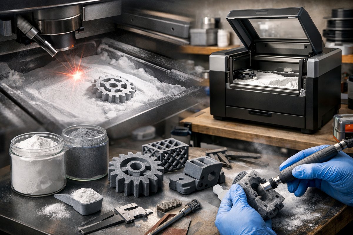
Selective Laser Sintering (SLS) transforms powdered polymers into rugged, functional parts by fusing layers with a laser. This hands-on guide walks you through selecting the right powder, setting up your desktop SLS printer, and mastering post-processing tools so you can bring complex geometries and durable prototypes to life.
Selective Laser Sintering is a powder-based additive manufacturing technique known for producing high-strength, heat-resistant parts without the need for support structures. Unlike filament or resin printing, SLS works by spreading a thin layer of polymer powder-typically nylon (PA12)-across a build chamber, then selectively melting that powder with a laser. Once one layer is sintered, the build platform lowers, fresh powder is spread, and the process repeats until your model emerges fully formed. The unsintered powder acts as support, enabling intricate geometries, interlocking assemblies, and fine lattices that other methods struggle to achieve.
Before you dive in, gather a suite of tools and materials designed for powder handling, laser sintering, and safe cleanup. Key components include:
• A desktop SLS 3D printer with reliable laser calibration and an enclosed build chamber.
• PA12 nylon powder certified for powder bed fusion.
• A powder sieving station or mesh sieve for reclaiming unsintered powder.
• An enclosed bead-blasting cabinet for removing fused powder residue.
• A high-efficiency particulate respirator mask and nitrile gloves to protect against airborne particles.
• A precision spatula or powder scraper to level each powder layer.
• A vacuum system with HEPA filtration for cleaning the build area.
Start with a solid CAD file optimized for SLS. Since SLS can handle complex details, you can design thin walls as low as 0.8 mm, but always check your printer’s specifications. Export your model in STL or 3MF format, then import it into your slicing software. Position multiple parts in the build envelope to maximize powder usage-nested arrangements and interlocking assemblies can be printed in a single run. Adjust these slicing parameters:
• Layer thickness: 80-120 microns delivers a fine surface finish but lengthens print time.
• Laser power and scan speed: Refer to your powder manufacturer’s datasheet for optimal sintering settings.
• Hatch spacing: Set the line spacing between adjacent laser paths to ensure strong interlayer bonding.
With the slice file prepared, fill the powder reservoir. Carefully pour or pump PA12 powder into the feed tank. Activate the mechanical spreader or roller-depending on your machine-to apply a consistent powder layer across the build platform. Proper leveling is critical: uneven thickness can lead to poor fusion or warping. Use a built-in leveling sensor if available, or visually inspect the layer edge for uniform coverage.
Once the chamber is sealed and inert gas flow (if needed) is initiated, launch the build. The laser will trace cross-sections of your part onto each powder layer. During the cycle, monitor the process through the chamber’s viewport or camera feed. Pay attention to:
• Temperature stability: Fluctuations of more than a few degrees Celsius can cause inconsistent fusion.
• Powder flow: Ensure the recoater arm moves without stalling or veering off track.
• Build time estimate: Larger batches may take tens of hours; plan multiple runs if you have tight deadlines.
When the build completes, allow the build chamber to cool-typically 2-4 hours-so parts can be handled without distortion. Unlock the build box and carefully remove it. Tip the excess powder into your sieving station or mesh sieve to reclaim any unsintered material. This reclaimed powder can be mixed with fresh feed at a ratio suggested by the powder supplier (often 30-50% reclaimed to fresh) for the next print cycle. Store reclaimed powder in sealed, labeled containers to prevent contamination.
Your printed parts will emerge coated in a fine layer of powder that’s fused only on outer surfaces. To reveal crisp details and a uniform finish, place parts inside an enclosed bead-blasting cabinet. Use glass bead media at low pressure (20-30 PSI) to gently abrade residual powder without damaging edges. This step:
• Improves surface roughness by smoothing microscopically uneven sinter lines.
• Evens out dull areas for a consistent matte finish.
• Opens up fine features that may be clogged with loose powder.
After bead blasting, rinse parts in isopropyl alcohol or compressed air to remove dust. Depending on your application, you can further enhance mechanical or aesthetic properties by:
• Applying a thin coat of epoxy or polyurethane sealer to improve chemical resistance.
• Painting with flexible, high-adhesion spray paints for visual prototypes.
• Bonding assemblies with cyanoacrylate or two-part epoxy using precision applicators.
To keep prints consistent, schedule regular maintenance:
• Clean recoater rails, optics windows, and filters after every build.
• Replace or replenish powder in controlled batches to avoid contamination.
• Calibrate laser power and recoater alignment quarterly, or after a defined number of build hours.
• Check chamber temperature sensors and gas flow meters to ensure stable sintering conditions.
By following these steps-from CAD optimization and powder handling to laser sintering and post-processing-you can harness SLS for durable, detailed prototypes or end-use parts. Whether you’re fabricating custom gears, complex lattice structures, or medical models, this method delivers mechanical strength, chemical resistance, and design freedom unmatched by other desktop processes. With investment in the right powder, protective equipment, and finishing tools, you’ll be ready to push the boundaries of functional additive manufacturing.