Location
Mount Vernon, WA 98274

Location
Mount Vernon, WA 98274
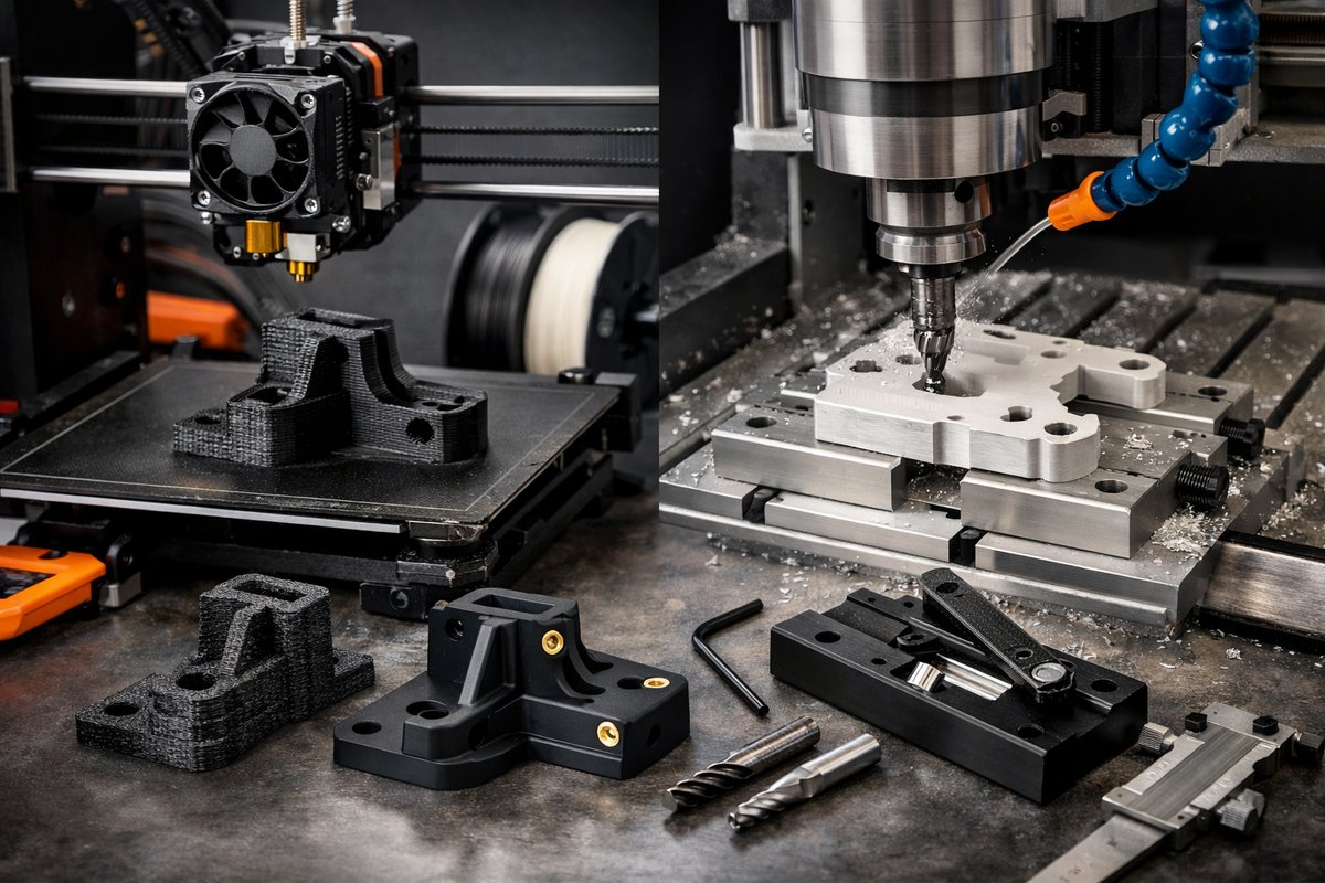
Discover a step-by-step workflow for combining desktop FDM 3D printing with CNC routing to achieve functional parts and jigs with sub-millimeter precision. Learn how the right nozzle, slicer settings, and end mill can transform rough prints into finished components ready for assembly.
In the ever-evolving world of manufacturing, hybrid workflows that marry additive and subtractive techniques have unlocked new levels of precision and creativity. By printing your initial shape with a cost-effective Fused Deposition Modeling (FDM) printer and then refining critical surfaces on a desktop CNC router, you gain both the speed of layering plastic and the accuracy of cutting metal. This guide dives deep into a practical technique: printing functional jigs or small mechanical parts in PETG, then surfacing key faces with a 1/8″ flat end mill to achieve crisp edges and flatness under 0.1 mm. You’ll walk away ready to tackle your own hybrid projects-no theory, just actionable steps and tool recommendations.
First, let’s set the stage with hardware. You’ll need a hobby-class FDM 3D printer that offers a removable build plate and supports a hardened steel nozzle. PETG is our filament of choice for its toughness and good layer adhesion, but you could substitute ABS for heat resistance or PLA if you prefer easy cleanup. On the subtractive side, a 3-axis desktop CNC router with a rigid gantry and a spoilboard works best. Make sure your CNC can comfortably hold a 1/8″ (3.175 mm) flat end mill and accommodate a part footprint at least 150 × 150 mm.
Next, dive into your CAD model. Design your jig, bracket, or prototype part as you would normally, but plan which surfaces demand higher precision. These might be mounting faces, mating surfaces, or shallow channels for alignment pins. Add small registration features-like dogbone pockets or locating nubs-to help you refasten the printed piece accurately in the CNC. Export your model in two formats: an STL for the print and a STEP or native CAD file for CNC toolpath generation.
On the printing side, start by installing a hardened steel nozzle around 0.4 mm or 0.5 mm. Hardened steel handles abrasive filaments and ensures consistent flow over long runs. Level your bed carefully and apply a thin coat of glue stick or your preferred adhesion aid. In your slicer settings, use a 0.2 mm layer height for a balance of detail and speed. Set infill around 30-40% if you need rigidity, or down to 15% for lighter jigs. Disable ironing features-surface finishing will be handled on the CNC. Print with a slower first-layer speed (20 mm/s) and a moderate overall speed (40-50 mm/s) to reduce layer misalignment.
After printing, allow the part to cool completely before removal. Clean off any brim or raft, and lightly sand sharp corners if necessary to avoid router bit crashes. Mount the print on your CNC spoilboard using double-sided tape or low-tack adhesive. Align registration features carefully under a camera or with a dial indicator to ensure your coordinate system matches the slicer origin.
Now, generate your toolpaths. Import the STEP or CAD model into your CAM software. Select a 1/8″ flat end mill with two flutes, carbide or high-speed steel. Set spindle speed around 10,000 RPM and a feed rate of 1,200 mm/min, adjusting based on your machine’s rigidity. Use a 0.5 mm step-down for the initial roughing pass and a 0.2 mm step-over for the finishing pass. Select climb milling mode to reduce plastic tearing. Focus your passes only on the pre-designated surfaces-this saves time and preserves print details on the rest of the part.
With the toolpaths loaded, run a dry run (air cut) to confirm the trajectories clear any tall features. Once satisfied, start the cut. Listen for a smooth, consistent chatter in the plastic-too loud or irregular may mean you need to slow your feed or adjust spindle speed. After the finishing pass, the machined surfaces should be glassy smooth, with crisp right-angle edges and flatness often better than 0.05 mm.
Finish the hybrid part by removing it from the CNC and detaching any tape or adhesive. Lightly brush off plastic chips with a soft brush. If you printed in PETG, you can apply a wipe of isopropyl alcohol on the machined faces for a clean, matte finish. Test-fit your part in its application: mounting holes will align perfectly, channels will seat components without play, and mating faces will clamp without shimming.
Leveraging this FDM-to-CNC workflow unlocks rapid iteration for functional prototypes, jigs, and small production runs. You gain the material variety of additive (PETG, ABS, PLA, specialty blends) and the surface quality of subtractive, all on affordable desktop equipment. No more settling for “good enough” tolerances when you can unlock sub-0.1 mm accuracy in key areas.
Ready to dive in? Gather these essential components and tools:
With those in hand, start designing your next jig, printing test coupons, and mastering the CNC surfacing step. You’ll soon discover how precision layers and precision cuts work in harmony to bring your ideas to life. This hybrid approach isn’t just a novelty-it’s a productivity booster, a tolerance guarantor, and an invitation to push the boundaries of what desktop machines can achieve. Embrace the discipline of subtraction atop the freedom of addition, and unlock a new chapter in your maker journey.












